- Build Your Infrared Remote Tester – Circuit Diagram & Parts List
- Build Your Own IR Remote Tester Circuit – 700Hz
- Long Range IR Transmitter Circuit Diagram – 10m+ Range
- Remote-Controlled Firecracker Igniter: Circuit & Design (3.5s)
- Build a Wireless Infrared Hand Switch Circuit – CA3140 Design
- Build Your Own Infrared Remote Control Circuit – 3A Triac Design
- Universal IR Switch Circuit Diagram – Build Your Own!
- Build Your Own IR Remote: 2N2222 Circuit Diagram
- IR Remote Control Tester: Circuit Diagram & Intensity Measurement
- IR Remote Jammer Circuit: Build Your Own Signal Disruptor
Remote-Controlled Firecracker Igniter: Circuit & Design (3.5s)
Description
Fireworks are typically ignited using a match or a candle. Immediate withdrawal from the area is necessary following the initiation of the firework's fuse. This ignition method is hazardous due to the consistent possibility of the device detonating before a safe distance is attained. The device detailed herein employs remote control, commonly utilized with television receivers or CD players, to trigger the burst of the firework. Consequently, the firework can be activated from a secure location using the circuit outlined below in conjunction with the remote control.
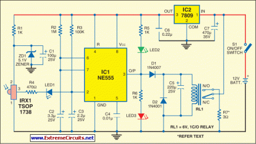
Within the diagram presented here, the standard state of the output from IC1 is low, and LED2 is illuminated while LED3 remains unlit. This indicates the circuit's readiness for operation. Upon pressing any button on the remote control, the output pin 3 of IRX1 (IR receiver module TSOP1738) transitions to a low state. This output is connected to pin 2 of IC1 via LED1 and resistor R4, initiating the monostable operation of IC1. The output of IC1 maintains a high status for a duration equivalent to 1.1×R2×C2. With the component values specified within the circuit diagram, this period amounts to approximately 3.5 seconds.
Circuit Diagram:
This activates relay RL1 and LED3 glows red while LED2 is extinguished. The ‘on’ state of LED3 signifies the impending detonation of the firework. R7 represents a small segment of a resistive heating element (220V, 1000W), positioned away from the electronic circuit and connected to the relay contacts via a robust electric cable. The resistance value of this short heating element section (R7) is between 3 and 3.5 ohms. A current of approximately 4 amperes flows through it when connected to a 12V battery. The passage of 4A through R7 for 3.5 seconds results in its substantial heating, which then ignites the firework.
The circuit is powered by a 12V, 7AH battery. IC2 provides approximately 9V for the operational functionality of the circuit. The circuit should be housed within a metallic enclosure to safeguard it from damage resulting from the bursting of the firework. The IR receiver and the two LEDs should be mounted on the front panel of the enclosure. Wiring and relay used in the circuit should be selected to ensure their ability to carry more than 5 amperes of current.
IC2
IC2 is a 9V DC power supply unit. It is a linear voltage regulator, typically based on a BC347 or similar integrated circuit. This IC efficiently converts the 12V battery voltage down to the required 9V for powering the rest of the circuit. It provides a stable and consistent output voltage, crucial for reliable operation of the sensitive electronic components. The IC’s internal circuitry regulates the current flow to maintain a steady 9V, despite variations in the battery voltage or current draw.
circuit from http://www.extremecircuits.net/2010/05/infrared-fire-cracker-igniter.html
