- Build Your Infrared Remote Tester – Circuit Diagram & Parts List
- Build Your Own IR Remote Tester Circuit – 700Hz
- Long Range IR Transmitter Circuit Diagram – 10m+ Range
- Remote-Controlled Firecracker Igniter: Circuit & Design (3.5s)
- Build a Wireless Infrared Hand Switch Circuit – CA3140 Design
- Build Your Own Infrared Remote Control Circuit – 3A Triac Design
- Universal IR Switch Circuit Diagram – Build Your Own!
- Build Your Own IR Remote: 2N2222 Circuit Diagram
- IR Remote Control Tester: Circuit Diagram & Intensity Measurement
- IR Remote Jammer Circuit: Build Your Own Signal Disruptor
Long Range IR Transmitter Circuit Diagram – 10m+ Range
Circuit Diagram
Description
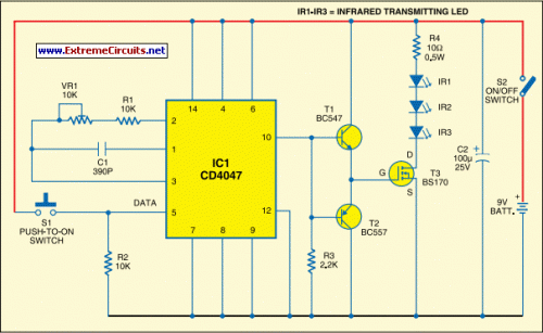
Numerous remote controls for IR devices typically function dependably within a distance of approximately 5 meters. Increasing the circuit’s intricacy to achieve dependable operation over a greater range, such as 10 meters, necessitates careful design. To double the operational range from 5 meters to 10 meters, it is necessary to amplify the transmitted power by a factor of four. Utilizing a highly focused IR beam (a very narrow beam) can be effectively accomplished by employing an IR laser pointer as the source of the IR signal.
The laser pointer is readily obtainable from various markets. However, when utilizing a laser pointer with a very restricted beam, meticulous attention must be paid, as even a slight movement of the device might alter the beam’s alignment and result in a loss of signal connection. A straightforward circuit has been constructed to provide a considerable range of operation. This circuit incorporates three infrared transmitting LEDs (IR1 through IR3) connected in series to enhance the radiated power output.
Furthermore, to bolster directivity and, consequently, the power density, it’s possible to integrate the IR LEDs within the reflector of a flashlight. To improve the circuit’s efficiency, a MOSFET (BS170) has been incorporated, functioning as a switch, much like a transistor. A 100µF reservoir capacitor C2 has been placed across the battery supply to mitigate any fluctuations during the ‘on’/‘off’ switching operations. Its benefits become particularly apparent when the IR transmitter is powered by standard batteries.
The capacitor C2 provides supplemental charge during the ‘switching on’ phase. Considering the MOSFET’s substantial capacitance observed across its gate-source terminals, a specialized drive arrangement has been implemented employing an npn-pnp Darlington pair of BC547 and BC557 (serving as emitter followers) to prevent distortion of the gate drive input. Data (CMOS-compatible) to be transmitted is used for modulating the 38 kHz frequency generated by CD4047 (IC1). Nevertheless, in the circuit depicted here, a tactile switch S1 has been utilized for modulating and transmitting the IR signal.
Assemble the circuit on a general-purpose printed circuit board (PCB). Utilize switch S2 for controlling power ‘on’/‘off’ functionality. Commercially available IR receiver modules, such as TSOP1738, could be deployed for efficient reception of the transmitted IR signals.
CD4047
The CD4047 is a versatile integrated circuit (IC) widely employed as a clock oscillator. It generates a precise 38 kHz frequency signal, essential for modulating the IR signal. The IC operates at a supply voltage of 5V and produces a stable clock output, suitable for driving various electronic circuits. It is a common component in IR remote control systems, where the 38 kHz frequency is used to transmit data. The CD4047 is a bipolar IC.
BC547/BC557
The BC547 and BC557 are dual-in-one NPN transistors, frequently utilized as emitter followers. They are small-signal transistors commonly found in low-power circuits. These transistors are used to amplify and buffer the output signal of another transistor, maintaining its characteristics while increasing its current capability. The use of these transistors as emitter followers provides enhanced current drive capability to the IR LEDs. The BC547 and BC557 are NPN bipolar transistors.
circuit from http://www.extremecircuits.net/2010/05/long-range-ir-transmitter.html
