- Build Your Infrared Remote Tester – Circuit Diagram & Parts List
- Build Your Own IR Remote Tester Circuit – 700Hz
- Long Range IR Transmitter Circuit Diagram – 10m+ Range
- Remote-Controlled Firecracker Igniter: Circuit & Design (3.5s)
- Build a Wireless Infrared Hand Switch Circuit – CA3140 Design
- Build Your Own Infrared Remote Control Circuit – 3A Triac Design
- Universal IR Switch Circuit Diagram – Build Your Own!
- Build Your Own IR Remote: 2N2222 Circuit Diagram
- IR Remote Control Tester: Circuit Diagram & Intensity Measurement
- IR Remote Jammer Circuit: Build Your Own Signal Disruptor
Build a Wireless Infrared Hand Switch Circuit – CA3140 Design
Description
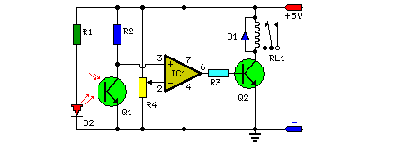
Household devices are frequently controlled utilizing switches and sensors, yet physical interaction with switches poses potential hazards due to the risk of short circuits. The circuit detailed herein avoids the necessity for any physical contact to operate the appliance. The operation requires merely moving one's hand between the infrared emitting diode (D2) and the phototransistor (Q1). The infrared radiation released by D2 is detected by Q1, triggering the concealed lock, flush system, or hand dryer, amongst other functionalities. This circuit demonstrates considerable stability and responsiveness when compared to other AC appliance control circuits. It is characterized by its simplicity, compact design, and affordability. The current consumption is minimal, measured in milliamperes. The circuit is based around an IC, CA3140, D2, the phototransistor, and several other discrete components. The CA3140 is a versatile integrated circuit often employed in sensor-based control systems due to its ability to amplify weak signals and provide switching capabilities. It typically incorporates comparator circuits, enabling it to accurately detect changes in input voltage, and can be configured as an open-collector switch, offering a robust method for controlling external devices.
Circuit Diagram:
Parts:
- R1 = 470R
- R2 = 100K
- R3 = 3.3K
- R4 = 10K
- D1 = 1N4007
- D2 = IR LED
- Q1 = L14F1
- RL = 5Vdc Relay
- IC = CA3140
- Q2 = BC548
Circuit Operation:
Upon application of a regulated 5V supply to the circuit, D2 generates infrared rays, which are received by the phototransistor Q1 if appropriately positioned. The collector of Q1 is connected to the non-inverting pin 3 of IC1. The inverting pin 2 of IC1 is connected to the voltage-divider configuration provided by resistor R4. Adjusting the reference voltage at pin 2 using this preset R4 also affects the sensitivity of the phototransistor. An operational amplifier IC1 amplifies the signal acquired from the phototransistor. Resistor R3 regulates the base current of transistor BC548 (Q2). The high output signal from IC1 at pin 6 drives transistor Q2 to energize relay RL1 and to activate the appliance, such as a hand dryer, via the relay contacts. The operation of the circuit is straightforward. To activate the appliance, simply interrupt the infrared beams falling on the phototransistor through the movement of one's hand. With the hand removed from the infrared beam, the appliance remains activated via the relay. Assemble the circuit on a general-purpose printed circuit board. Identify the resistors through color coding or using a multimeter. Confirm the correct polarity and pin configuration of the IC and mount it on the board. Following soldering the circuit, connect the +5V power supply to it.
