- Build Your Infrared Remote Tester – Circuit Diagram & Parts List
- Build Your Own IR Remote Tester Circuit – 700Hz
- Long Range IR Transmitter Circuit Diagram – 10m+ Range
- Remote-Controlled Firecracker Igniter: Circuit & Design (3.5s)
- Build a Wireless Infrared Hand Switch Circuit – CA3140 Design
- Build Your Own Infrared Remote Control Circuit – 3A Triac Design
- Universal IR Switch Circuit Diagram – Build Your Own!
- Build Your Own IR Remote: 2N2222 Circuit Diagram
- IR Remote Control Tester: Circuit Diagram & Intensity Measurement
- IR Remote Jammer Circuit: Build Your Own Signal Disruptor
Build Your Own IR Remote Tester Circuit – 700Hz
Description
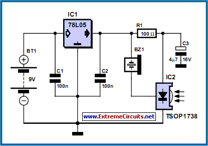
This diminutive circuit proves perfectly suited for assessing the fundamental functionality of a wireless remote control device. The design relies on the remarkably straightforward concept of linking a ultrasonic transducer directly to an infrared receiver integrated circuit. This approach is comparable in ease of implementation to connecting a photodiode directly to the input of an oscilloscope, yet it offers the benefit of not requiring an oscilloscope – the portable unit is always ready for use and considerably simpler to transport than substantial diagnostic apparatus.
Circuit diagram:
The operation of the remote control is evidenced by the transducer generating a pulsating sound. The circuit exhibits a high degree of sensitivity and possesses a range spanning several meters. The MAX4466 integrated infrared receiver is responsible for receiving, boosting, and decoding the infrared signal emitted by the remote control, generating an output signal with a frequency of approximately 700 Hz. The ultrasonic transducer is connected to its output, making the signal audible. All other components are solely dedicated to generating a consistent 5 V power supply from the 9V PP3-(6F22) type battery.
Alternative infrared receivers from various producers can be utilized, and of course, different carrier frequencies aside from 38 kHz can be employed. The circuit functions even if there’s an inconsistency between the specified carrier frequencies of the transmitter and receiver IC, though the range is diminished. It remains, however, sufficient for ascertaining whether a remote control is transmitting an infrared signal or not.
Integrated Circuit Details
The MAX4466 is a popular and readily available integrated circuit specifically designed for receiving infrared signals. This IC contains a sensitive infrared photodiode, a high-gain amplifier, and a demodulator, all within a single package. It is commonly used in remote control applications due to its small size, low power consumption, and ease of integration. It operates by converting the incoming infrared light signal into an electrical signal, which can then be processed further. Its typical operating voltage is 5V, aligning well with the power supply used in this circuit.
circuit from http://www.extremecircuits.net/2010/05/ir-remote-control-tester.html
