- Build a 3.3V Step-Down Converter with TPS62000
- Build a 13V Voltage Doubler: Boost Your Circuits!
- Build a -5V Circuit: 9V Battery & 555 Timer Design
- Powering 25W Loads: CMOS to 12V Circuit Design
- DC to DC Converter: Build a 12V High Voltage Oscillator
- 12V Regulated Inverter Circuit Diagram & Build Guide
- Step-Down Converter: TPS6420x Design
- Dual Voltage Inverter Circuit: 5V-20V to +/-2.5V to +/-10V
Dual Voltage Inverter Circuit: 5V-20V to +/-2.5V to +/-10V
Description
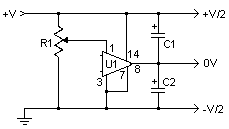
This straightforward and affordable circuit generates a dual (positive and negative) voltage supply from a singular input source. Consequently, it proves exceptionally valuable for powering operational amplifiers and other circuits that necessitate a bipolar output from a single power source. The circuit operates effectively with an input voltage ranging from approximately 5V to 20V, yielding an output spanning from roughly -2.5V to -10V.Circuit diagram
Parts
- R1 1M Linear Pot
- C1,C2 15uf 25V Electrolytic Capacitor
- U1 LM380 Audio Amp Chip
- MISC Heatsink For U1, Binding Posts (For Input/Output), Wire, Board
Notes
- 1. U1 generates approximately 1W of heat and thus necessitates a heatsink for proper operation.
- 2. R1 is utilized to balance the outputs. When initially implementing this circuit, it should be set to its midpoint and then fine-tuned utilizing a voltmeter. Measure each output while adjusting the potentiometer. The circuit achieves calibration when both outputs display identical voltage values (either positive or negative).
Integrated Circuits – LM380
The LM380 is a versatile and widely utilized audio amplifier integrated circuit. It is renowned for its relatively low cost and ease of use, making it a popular choice for hobbyists and professionals alike. This IC comprises a dual operational amplifier, providing two independent amplifier stages within a single package. It typically operates from a supply voltage of 6V to 30V and offers a respectable output current capability. The LM380 is frequently employed in applications such as audio preamplifiers, small-signal amplifiers, and audio power amplifiers. Its performance characteristics include a gain of approximately 20dB, a slew rate of 1.5V/µs, and a bandwidth of 200kHz. It’s a robust chip, well-suited to a variety of low-power audio amplification tasks.
