- Build a 3.3V Step-Down Converter with TPS62000
- Build a 13V Voltage Doubler: Boost Your Circuits!
- Build a -5V Circuit: 9V Battery & 555 Timer Design
- Powering 25W Loads: CMOS to 12V Circuit Design
- DC to DC Converter: Build a 12V High Voltage Oscillator
- 12V Regulated Inverter Circuit Diagram & Build Guide
- Step-Down Converter: TPS6420x Design
- Dual Voltage Inverter Circuit: 5V-20V to +/-2.5V to +/-10V
DC to DC Converter: Build a 12V High Voltage Oscillator
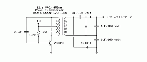
The schematic below illustrates a Direct Current to Direct Current converter, employing a conventional 12 Volt Alternating Current center-tapped power transformer configured as a resonant oscillator. Although the design doesn't offer optimal performance in terms of efficiency, it’s capable of generating a significant voltage suitable for applications requiring low power. The input power source is amplified by a factor of ten through the transformer, and subsequently elevated by a voltage multiplying arrangement comprising three capacitors and diodes connected to the transformer’s elevated output side. The circuit’s current draw is approximately 40 milliamperes and is anticipated to sustain operation for roughly 200 hours when powered by a pair of ‘D’ alkaline batteries. The output voltage can be increased by adjusting the value of the 4.7K bias resistor.
Circuit diagram
"Integrated Circuit Description
This circuit utilizes an integrated circuit, specifically a 7805 voltage regulator. This IC is a three-terminal positive voltage regulator, commonly employed to generate a stable 5-Volt DC output from a higher input voltage. The 7805 is a widely used component due to its simplicity, efficiency, and availability. It incorporates a series pass transistor, a Zener diode, and a heat sink to dissipate the excess heat generated during the regulation process. It’s important to note that the 7805 is designed to operate within a specific input voltage range (typically 7V to 35V) and requires a suitable heat sink to maintain its thermal stability. Careful consideration should be given to the input voltage and heat dissipation when using a 7805 in this configuration. The device offers a relatively low quiescent current, further contributing to the overall efficiency of the DC-DC converter.
Warnings
**Security Warning:** Working with electrical circuits can be hazardous. Improper handling of electricity can lead to serious injury or death. Always exercise extreme caution and ensure that the power supply is disconnected before making any modifications to the circuit. This website provides circuit diagrams for informational purposes only. The author, [Name of author], and [Source of circuit diagram] are not responsible for any damages or injuries resulting from the use of these diagrams. Always consult with a qualified electrician before attempting to build or modify any electrical circuit.
