- Build a 3.3V Step-Down Converter with TPS62000
- Build a 13V Voltage Doubler: Boost Your Circuits!
- Build a -5V Circuit: 9V Battery & 555 Timer Design
- Powering 25W Loads: CMOS to 12V Circuit Design
- DC to DC Converter: Build a 12V High Voltage Oscillator
- 12V Regulated Inverter Circuit Diagram & Build Guide
- Step-Down Converter: TPS6420x Design
- Dual Voltage Inverter Circuit: 5V-20V to +/-2.5V to +/-10V
Build a -5V Circuit: 9V Battery & 555 Timer Design
Description
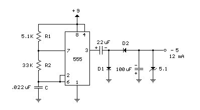
A NE555 timer module is utilized to generate a pulsed waveform, creating a negative voltage relative to the negative battery terminal. Upon the timer's output at pin 3 transitioning to a positive signal, a 22 μF capacitor charges through the diode (D1) up to approximately 8 volts. When the output shifts to ground, the 22 μF capacitor discharges via the second diode (D2) and charges the 100 μF capacitor, ultimately resulting in a negative voltage that can fluctuate over several cycles, reaching around -7 volts. This voltage rise is constrained by the 5.1 volt Zener diode, functioning as a voltage stabilizer. The circuit consumes roughly 6 milliamps from the battery when the Zener diode is absent, and increases to approximately 18 milliamps with the diode connected. The accessible output current for the load is approximately 12 milliamps. To achieve a symmetrical +/- 5 volt supply, a 5.1 volt Zener diode and a 330 ohm resistor could be incorporated to regulate the +9 volt supply to +5 volts at a current of 12 mA. The battery drain would then be around 30 mA.
NE555 Timer Module
The NE555 is a versatile integrated circuit (IC) primarily employed as a timer, oscillator, and voltage regulator. It's a three-terminal IC that includes a comparator, a precision voltage reference, and a timing capacitor. In this circuit, it's utilized to generate a timed pulse sequence, creating the variable negative voltage. The NE555 itself is a monolithic integrated circuit, fabricated on a silicon substrate, and contains a large number of interconnected transistors and diodes. It’s a commonly used component due to its ease of use and relatively low cost. It’s typically operated with an external capacitor for timing and utilizes its internal comparator to generate the desired waveform.
