- Build a 3.3V Step-Down Converter with TPS62000
- Build a 13V Voltage Doubler: Boost Your Circuits!
- Build a -5V Circuit: 9V Battery & 555 Timer Design
- Powering 25W Loads: CMOS to 12V Circuit Design
- DC to DC Converter: Build a 12V High Voltage Oscillator
- 12V Regulated Inverter Circuit Diagram & Build Guide
- Step-Down Converter: TPS6420x Design
- Dual Voltage Inverter Circuit: 5V-20V to +/-2.5V to +/-10V
Build a 13V Voltage Doubler: Boost Your Circuits!
Description
Many small electronic devices function using batteries. Some of these devices require voltages exceeding those provided by standard batteries to operate efficiently. Consequently, when a battery of the desired voltage isn't accessible, we must connect additional cells in series to increase the direct current voltage. This compromises the fundamental concept of miniaturization. A straightforward solution to this problem involves utilizing a voltage multiplier, provided the device under consideration can operate at a modest current.
Here we present a low-power voltage multiplying circuit that can be easily used with devices needing higher voltage than a standard battery but with low operating current. The circuit is relatively simple, employing just a few components. Nevertheless, the output efficiency ranges from 75 to 85 percent across its operating voltage range. The incoming battery voltage is nearly doubled at the output of the circuit.
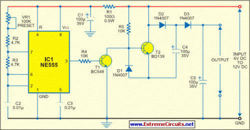
Within this design, IC1 is configured as an astable multivibrator to generate rectangular pulses at approximately 10 kHz. The frequency and duty cycle of these pulses can be adjusted using potentiometer VR1. These pulses are then applied to switching transistors T1 and T2 to drive the output section, which is arranged as a voltage-multiplying circuit. The amplified voltage is available across capacitor C5. During each pulse occurrence, the high-level signal forces T1 into its saturation, keeping transistor T2 switched off.
Circuit diagram:
Thus, transistor T1 charges capacitor C4 via the path formed by diodes D2 and D1 to a voltage level slightly below the supply. However, during the low period of the pulse, transistor T1 is cut off while transistor T2 is driven into saturation. Now, transistor T2 elevates the charge on the negative terminal of capacitor C4 by an amount equivalent to the supply voltage. Consequently, an equal amount of charging occurs on capacitor C5 via diode D3.
This multiplying action increases the total voltage across capacitor C5 to nearly double the input voltage. If the output signal from the pulse generator is maintained with sufficient amplitude and frequency, the output voltage and current remain constant and satisfy the needs of the load. Even with a half-wave function, this circuit exhibits minimal ripple voltage. If the connected load doesn’t demand high current, the efficiency can be anticipated within the upper 90 percent ranges.
Because the input voltage is multiplied, the current drawn from the input power supply is also doubled at the input but halved at the output. A key caution is that if the multivibrator’s frequency is high, the output may experience interference superimposed upon the DC voltage. In such circumstances, the frequency must be tuned favorably through experimentation and actual load connections. This compact circuit can be assembled on a general-purpose printed circuit board. If all components are surface-mount type, the entire module can be genuinely miniaturized.
EFY Lab note.
During testing with an input of 8V and a 1.25mA load current, the measured output voltage was approximately 13V.
