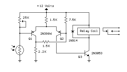
- Automated Dusk-to-Dawn Lamp Circuit Diagram
- Build a Light Sensor Circuit with an LED and Op-Amp
- Automatic Emergency Light Circuit Design: 555, LM317 & X1
- Automatic Light Controller with 7806 – Build Your Own!
- Pinewood Finish Line: Circuit Design & Lamp Illumination
- Schmitt Trigger Street Light Circuit Diagram – 8V, 4V Switching
- Simple Optical Switch with 555 Inverter
- Build Your Own Light/Dark Detector Circuit – 100K Sensitivity
- LED Photo Sensor: Build a 5V to 2V Light Detector Circuit
Schmitt Trigger Street Light Circuit Diagram – 8V, 4V Switching
Circuit diagram
Description
This circuit represents a Schmitt Trigger design, intended to manage a street lamp, accepting input from a cadmium sulfide photocell and controlling a relay for operation at sunrise and sunset. The construction involved a 120 ohm/12 volt relay, and performance was evaluated using a lamp dimmer, though the relay was not connected to an exterior light source.
The photocell is protected from surrounding light to prevent erroneous switching, typically positioned above the lamp on a reflector, pointed upwards towards the sky to avoid detection of the lamp’s illumination and subsequent triggering of the relay.
The photocell is connected in series with a potentiometer, allowing voltage adjustment at the junction (and transistor base) to approximately half of the supply voltage, at the target ambient light level. Two PNP transistors are utilized with a common emitter resistor for positive feedback, ensuring that as one transistor turns on, the other will turn off, and vice versa.
Under dark conditions, the photocell exhibits a higher resistance than the potentiometer, resulting in a voltage at Q1 exceeding the base voltage at Q2, which then activates Q2 and consequently triggers the relay.
Schmitt Trigger IC Description
Schmitt Triggers are integrated circuits (ICs) specifically designed to provide switching functions based on input voltage levels. They operate as comparator circuits, generating a digital output when the input voltage crosses a defined threshold. These ICs are frequently employed in applications needing reliable switching based on signal levels, such as in signal conditioning, level detection, and triggering circuits. Common examples include the CD4010 and CD4040 series, which are widely used for their versatility and ease of implementation. Their relatively simple construction and low component count make them ideal for designing robust and reliable switching circuits. The IC’s internal circuitry includes hysteresis, which provides stability and prevents oscillations. The specified ICs contain a voltage comparator, a hysteresis gate, and a transistor stage. These components work together to achieve the desired switching behavior.
Cadmium Sulfide Photo Cell Description
A cadmium sulfide (CdS) photocell is a semiconductor device that converts light intensity into an electrical current. It's a variable resistor; its resistance decreases as light intensity increases. CdS cells are commonly utilized in light-sensitive circuits and as light detectors in various applications. These cells offer a linear response to light, providing a straightforward method for measuring light levels. The key characteristic of CdS cells is its temperature sensitivity, which can cause resistance changes with varying temperatures. They come in different sizes and sensitivities, with models offering varying light-to-current conversion ratios. These components are frequently used to control automated lighting systems, light meters, and optical switches. The cells are typically encased in a protective coating to safeguard the semiconductor material from environmental elements. They are available in several formats, including small through-hole packages and surface-mount devices. CdS photocells are manufactured through a chemical vapor deposition process. Their reliability and cost-effectiveness contribute to their wide adoption in numerous electronic devices.
The switching points are approximately 8 volts and 4 volts, based on the resistor values presented, but could be adjusted more closely by utilizing a lower value for the 7.5K resistor. Substituting a 3.3K resistor would shift the levels to approximately 3.5 and 5.5 for a range of 2 volts instead, enabling the relay to activate and deactivate nearer the target ambient light level. The potentiometer would then need to be recalibrated to ensure a voltage of roughly 4.5 at the desired ambient condition.
