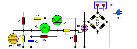
- Automated Dusk-to-Dawn Lamp Circuit Diagram
- Build a Light Sensor Circuit with an LED and Op-Amp
- Automatic Emergency Light Circuit Design: 555, LM317 & X1
- Automatic Light Controller with 7806 – Build Your Own!
- Pinewood Finish Line: Circuit Design & Lamp Illumination
- Schmitt Trigger Street Light Circuit Diagram – 8V, 4V Switching
- Simple Optical Switch with 555 Inverter
- Build Your Own Light/Dark Detector Circuit – 100K Sensitivity
- LED Photo Sensor: Build a 5V to 2V Light Detector Circuit
Automated Dusk-to-Dawn Lamp Circuit Diagram
Description
This apparatus enables the illumination of one or more bulbs at dusk and automatically switches them off at dawn. Q1 and Q2 function as a triggering mechanism for the SCR, generating brief pulses at a frequency of 100Hz. The duration of these pulses is adjustable via R2 and C1. When light strikes R1, the photoresistor assumes a remarkably low resistance, effectively shorting C1 and preventing circuit activation. Conversely, within darkness, R1’s resistance value increases significantly, thereby permitting circuit operation.
More about components
The circuit incorporates several integrated circuits for optimal performance. The BD327 and BD337 transistors serve as switches, controlling the flow of current within the circuit. These transistors are typically used in switching applications, controlling the operation of larger components or loads. The TIC106D is a timing IC, providing precise timing signals essential for the circuit's functionality. It’s frequently employed in applications requiring accurate timing control, such as pulse generation or frequency modulation.
Circuit Diagram:
Parts:
- R1 = LDR
- R2 = 100K
- R3 = 200K
- R4 = 470R
- R5 = 12K
- R6 = 1K
- R7 = 470R
- C1 = 10nF-63V
- D1 = TIC106D
- D2 = 1N4007
- D3 = 1N4007
- D4 = 1N4007
- D5 = 1N4007
- Q1 = BD327
- Q2 = BD337
- SK1 = Female Mains Socket
Notes:
- R3 facilitates fine adjustment of the operating threshold, while the maximum value for R2 can be elevated to 150K.
- Multiple lamps, connected in parallel, can be integrated into the circuit, provided the total power dissipation of the load remains within the range of approximately 300 - 500W.
- PL1 can be excluded, and the input mains supply wires can be connected in parallel to any switch controlling the lamps. In this scenario, if the switch is left open, the circuit will be able to drive the lamps; if the switch is closed, the lamps will illuminate, and the circuit will be bypassed.
- Warning! The circuit is connected to 230Vac mains, and several components on the circuit board are subjected to lethal potential! Avoid touching the circuit when plugged in and enclose it within a plastic casing.
