- Clap-Activated Relay Circuit: Diagram & Build Guide
- Room Noise Detector Circuit: Build Your dB Threshold!
- Build Your Own 1.8KHz Whistle Responder Circuit
- Whistle Responder Circuit: Build Your Own Beeping Gadget
- Voice Activated Switch: Mastering R6 for Superior VOX Control
- Build Your Key Finder: A 3-4kHz Circuit
- Room Noise Detector: Build Your dB Threshold Circuit
- Sound-Activated Relay Circuit: Build Your Responsive Project
- Whistle Circuit: Build a Toggle Flip-Flop with Filters
Whistle Responder Circuit: Build Your Own Beeping Gadget
Beeps when it hears your whistle
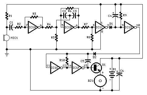
Circuit diagram:
Parts:
- R1 22K 1/4W Resistor
- R2 10K 1/4W Resistor
- R3 4M7 1/4W Resistor
- R4, R8 100K 1/4W Resistors
- R5 220R 1/4W Resistor
- R6 330K 1/4W Resistor
- R7 47K 1/4W Resistor
- R9 2M2 1/4W Resistor
- R10 1M5 1/4W Resistor
- C1, C5 47nF 63V Polyester or Ceramic Capacitors
- C2, C3 10nF 63V Polyester Capacitors
- C4, C6 1µF 63V Electrolytic Capacitors
- D1, D2 1N4148 75V 150mA Diodes
- IC1 4049 Hex Inverter IC
- Q1 BC337 45V 800mA NPN Transistor
- MIC1 Miniature electret microphone
- BZ1 Piezo sounder (incorporating 3KHz oscillator)
- B1 2.8 or 3V Battery (see notes)
Device purpose:
Approximately fifteen years ago, small key-holders were frequently seen emitting a short, periodic beep for a couple of seconds after someone whistled. These particular devices utilized a specialized integrated circuit and were therefore unsuitable for amateur construction. The current circuit design is based on a general-purpose hex-inverter CMOS IC, and, employing small components and button clock-type batteries, can be housed within a matchbox. It functions primarily as a novelty gadget, although many potential applications are possible.
Circuit operation:
This device produces intermittent beeps for around two seconds when a person within a range of approximately ten meters emits a whistle.
The initial two inverters found within IC1 are employed as audio amplifiers. IC1A consistently amplifies the signal picked up by the miniature electret microphone, and IC1B serves as a band-pass filter, its central frequency set around 1.8KHz. This filter is necessary to select the specific frequency of the whistle, preventing the beeper from operating due to other frequencies. IC1C is configured as a Schmitt trigger, converting the incoming audio signal into a square wave. IC1D provides a monostable timing circuit, driving the astable formed by IC1E & IC1F. This oscillator generates a 3 to 5Hz square wave that feeds Q1 and BZ1, resulting in the intermittent beeper's operation.
Notes:
- Power supply range: 2.6 to 3.6 Volts.
- Standing current: 150µA.
- Depending on the dimensions of your enclosure, a selection of battery types can be utilized:
- 2 x 1.5 V batteries, type AA, AAA, AAAA, button clock-type, photo-camera type & others.
- 2 x 1.4 V mercury batteries, button clock-type.
- 1 x 3 V or 1 x 3.6 V Lithium cells.
circuit from http://www.redcircuits.com/
