- Clap-Activated Relay Circuit: Diagram & Build Guide
- Room Noise Detector Circuit: Build Your dB Threshold!
- Build Your Own 1.8KHz Whistle Responder Circuit
- Whistle Responder Circuit: Build Your Own Beeping Gadget
- Voice Activated Switch: Mastering R6 for Superior VOX Control
- Build Your Key Finder: A 3-4kHz Circuit
- Room Noise Detector: Build Your dB Threshold Circuit
- Sound-Activated Relay Circuit: Build Your Responsive Project
- Whistle Circuit: Build a Toggle Flip-Flop with Filters
Clap-Activated Relay Circuit: Diagram & Build Guide
Description
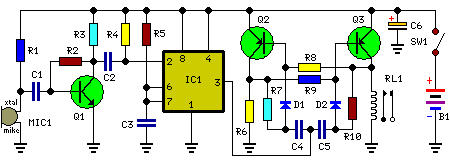
This circuit was designed to activate a relay through a hand clap. Subsequent claps will deactivate the relay. A notable and uncommon feature of this project is its operation using a 3V battery. The circuit’s sensitivity was deliberately diminished, ensuring predictable operation. Consequently, a forceful hand clap is necessary for dependable on-off switching. Q1 functions as an audio amplifier. IC1, a 7555 CMOS IC, serves as a timer, configured as a monostable, offering a clear output signal and a suitable delay period to facilitate the proper operation of the following bistable circuit. A discrete-components arrangement comprising Q2, Q3 and associated components was implemented for direct Relay driving and to support 3V supply operation.
Circuit Diagram:
Parts:
- R1 = 12K
- R2 = 1M
- R3 = 6.8K
- R4 = 220K
- R5 = 2.2M
- R7 = 100K
- R8 = 22K
- R9 = 6.8K
- R10 = 100K
- Q1 = BC550C
- Q2 = BC328
- Q3 = BC328
- C1 = 220nF-63V
- C2 = 22nF-63V
- C3 = 220nF-63V
- C4 = 22nF-63V
- C5 = 22nF-63V
- C6 = 47uF-25V
- D1 = 1N4148
- D2 = 1N4148
- B1 = 3V Battery
- IC1 = 7555 CMOS IC
- RL1 = DIL Reed-Relay SPDT
- SW1 = SPST Switch
- MIC1 = Electret Mic
Notes:
A small DIL 5V reed-relay was employed despite the 3V supply. Many instances of this equipment type were evaluated, and all were found capable of activating with a coil voltage within the range of 1.9 - 2.1V. Coil resistance values ranged from 140 to 250 Ohm. The circuit's standby current consumption is less than 1mA. When the Relay is energized, current draw increases to approximately 20mA.
