- Electronic Torricelli Barometer Circuit Diagram – Build Your Own!
- Build Your 1.8-220V DC/AC Voltage Detector Circuit
- Build Your Pulse Generator: 1.5V Circuit Explorer
- Signal Tracer Injector Circuit: Fault Find Audio & Radio
- Build Your Own PIC Servo Tester Circuit Diagram
- Build Your dB Meter: 3-Level Sound Indicator
Build Your 1.8-220V DC/AC Voltage Detector Circuit
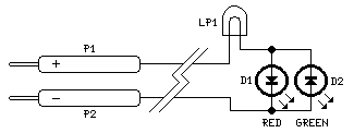
This schematic identifies voltages from 1.8 to 220 Volts DC or AC.
Circuit Diagram
Components:
- D1 5 or 3mm. Red Light-Emitting Diode
- D2 5 or 3mm. Green or Yellow Light-Emitting Diode
- LP1 220V 6W Filament Bulb
- P1 Red Sensor Probe
- P2 Black Sensor Probe
Device Functionality:
This design isn't a mere amusement; its practicality, simplicity, and affordability make it a worthwhile project. When the red sensor probe is linked to a DC positive voltage supply and the black probe to the negative terminal, the red LED activates. Reversing the polarity causes the green LED to illuminate. Connecting the probes to an alternating current source results in both LEDs becoming illuminated. The filament bulb regulates the current flowing to the LEDs, limiting it to approximately 40mA at 220V AC. The filament lamp’s filament begins to glow, its brightness increasing as the voltage level rises. Consequently, due to the lamp’s filament’s behavior, any voltage between 1.8 and 220 Volts can be measured without needing to alter the values of the constituent parts.
Important Considerations
Dual-color LEDs (Red and Green) can be substituted for D1 and D2.
Safety Warnings
This circuit involves electrical components and potentially hazardous voltages. Exercise extreme caution while operating this device. Always ensure proper insulation and disconnect the power source before making any adjustments or modifications. Never touch exposed electrical connections while the circuit is energized. This device is intended for educational and experimental purposes only. The author assumes no responsibility for any damages or injuries resulting from the misuse or improper operation of this circuit. Consult with a qualified electrician for any electrical work.
circuit from http://www.redcircuits.com/
