- Build Your Inspiring 240VAC Mains Smoke Detector Alarm Circuit
- Build a Powerful 200mA Security Siren Circuit
- 3V Mini Alarm Circuit Diagram & Build Guide
- Laptop Alarm Circuit: Build Your Theft Protection Scheme
- DIY Motion-Activated Alarm Circuit with 100W Lamp
- 5-Digit Alarm Keypad: Build Your Secure Circuit Diagram
- Build Your 4-Digit Alarm Keypad Circuit Diagram
- Build Your 20-Minute Battery Burglar Alarm Schematic
- Enhanced Shed Alarm Circuit Diagram with 30-Second Delays
- Simple Fire Door Alarm Circuit Design & Timing Control
- Simple Shop Alarm: Build a 3-5 Second Beep Timer
- Four Transistor Alarm Circuits: Design & Build Your Own!
- 12 Small CMOS Alarm Circuits Diagrams – Build Your Own!
- Build Your 12V Burglar Alarm Circuit Diagram
- Build Your 30-Second Alarm: Circuit Diagram & Design
Build Your 30-Second Alarm: Circuit Diagram & Design
Description
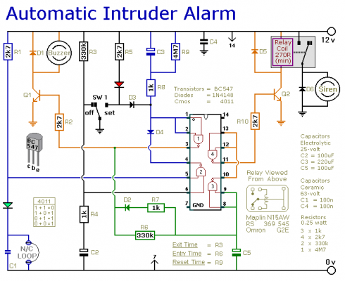
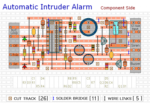
This represents a straightforward single-zone security system circuit. It incorporates automatic Exit and Entry delays along with a timed Bell/Siren deactivation. It's intended for utilization with conventional, normally-closed input devices – including magnetic reed contacts – miniature switches – foil sheeting – and Passive Infrared (PIR) sensors. However, it can be readily adapted to accommodate normally-open triggering devices – such as pressure pads.
Integrated Circuit Detail
The circuit extensively uses the NE555 timer IC. This device functions as a precise time delay generator, controlling the duration of the Exit and Entry delays, as well as the Bell/Siren deactivation. The NE555’s positive input pin (pin 8) is connected to a resistor, creating a delay circuit. The frequency of the 555 timer is carefully set to provide accurate timing for the alarm system. It’s crucial to note that the NE555 is a versatile and commonly used IC for timing applications, known for its stability and ease of use. This particular IC is a monolithic integrated circuit, providing several key functionalities, including accurate timing and frequency generation.
Schematic Diagram
It’s uncomplicated to implement. Initially, verify that the building’s security is intact and the green LED is illuminated. Subsequently, move SW1 to the “set” position, and the red LED will activate. You now have approximately 30 seconds to vacate the building. Upon returning and opening the door, the Buzzer will emit a sound. Following this, you have around 30 seconds to reposition SW1 to the “off” position. If this action isn’t taken within the specified timeframe, the relay will energize, and the Siren will activate.
The maximum duration for which the Siren will remain active isn’t predetermined. The 15-minute deactivation timer commences its operation only when the normally-closed loop has been restored. While the loop remains open, the Siren will continue to sound.
To configure your Siren to deactivate after 15 minutes, a simple modification to the triggering circuit is all that’s required. Once the alarm is initiated, the cut-off timer will begin running, and the Siren will cease operation after 15 minutes, irrespective of the loop’s state.
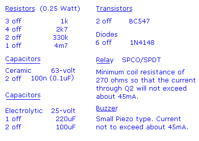
Due to manufacturing variations – the precise length of any delay depends on the characteristics of the components actually used in your circuit. However, by adjusting the values of R3, R6 & R9, you can tailor the Exit, Entry and Bell Cut-Off times to meet your specific needs. Increasing the values extends the duration – while decreasing them reduces it.


