- Build Your Inspiring 240VAC Mains Smoke Detector Alarm Circuit
- Build a Powerful 200mA Security Siren Circuit
- 3V Mini Alarm Circuit Diagram & Build Guide
- Laptop Alarm Circuit: Build Your Theft Protection Scheme
- DIY Motion-Activated Alarm Circuit with 100W Lamp
- 5-Digit Alarm Keypad: Build Your Secure Circuit Diagram
- Build Your 4-Digit Alarm Keypad Circuit Diagram
- Build Your 20-Minute Battery Burglar Alarm Schematic
- Enhanced Shed Alarm Circuit Diagram with 30-Second Delays
- Simple Fire Door Alarm Circuit Design & Timing Control
- Simple Shop Alarm: Build a 3-5 Second Beep Timer
- Four Transistor Alarm Circuits: Design & Build Your Own!
- 12 Small CMOS Alarm Circuits Diagrams – Build Your Own!
- Build Your 12V Burglar Alarm Circuit Diagram
- Build Your 30-Second Alarm: Circuit Diagram & Design
Simple Fire Door Alarm Circuit Design & Timing Control
Description
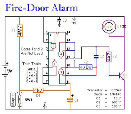
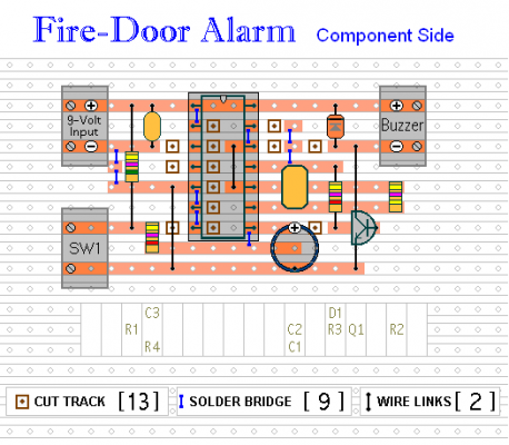
This represents a straightforward - easily constructed - refrigerator-style alarm circuit. A small 9-volt battery was utilized for power provision. However, the circuit functions effectively within a voltage range of 5 to 15 volts; it’s crucial to select a buzzer appropriate for the voltage being employed. The circuit’s standby current is minimal – consequently, the battery’s lifespan is notably extended.
It is vitally important that fire-doors remain securely closed at all times. Should they be left ajar – they cease to fulfill their intended purpose. When SW1 is connected to the fire-door, the alarm circuit permits the door’s opening and closing operations without triggering the Buzzer. Nevertheless, if the door is left open for more than approximately 30 seconds, the Buzzer will initiate a sequence of brief warning tones.
The duration of the initial delay is determined by the values of R1 and C1. The rate and length of the beeps are adjusted by R2 and C2. With the values displayed in the diagram, after an initial delay of about 30 seconds, the Buzzer will activate and deactivate at roughly half-second intervals.
A magnetic reed-switch was depicted as SW1 – but you can utilize any type of switch compatible with your specific application. If you have multiple fire-doors requiring protection, you can implement more than one switch; simply wire all of your switches in series.
Changing the Output Time
Generally speaking, the length of the initial delay is directly proportional to the values of R1 and C1. In other words, if you increase the value of either R1 or C1 by a factor of two, the length of the initial delay will also double. Conversely, if you reduce the value of either R1 or C1 by a factor of two, the length of the initial delay will be halved.
The same relationship applies to the duration of the beep. Generally speaking, the length of the beep is proportional to the values of R2 and C2. In other words, if you double the value of either R2 or C2, the length of the beep will also double. If you halve the value of either R2 or C2, the length of the beep will be halved.
For accurate output timing, a variable resistor (or preset) should be employed in place of R2. Then, adjust the resistor until the desired beep duration is achieved.


