- Build Your Inspiring 240VAC Mains Smoke Detector Alarm Circuit
- Build a Powerful 200mA Security Siren Circuit
- 3V Mini Alarm Circuit Diagram & Build Guide
- Laptop Alarm Circuit: Build Your Theft Protection Scheme
- DIY Motion-Activated Alarm Circuit with 100W Lamp
- 5-Digit Alarm Keypad: Build Your Secure Circuit Diagram
- Build Your 4-Digit Alarm Keypad Circuit Diagram
- Build Your 20-Minute Battery Burglar Alarm Schematic
- Enhanced Shed Alarm Circuit Diagram with 30-Second Delays
- Simple Fire Door Alarm Circuit Design & Timing Control
- Simple Shop Alarm: Build a 3-5 Second Beep Timer
- Four Transistor Alarm Circuits: Design & Build Your Own!
- 12 Small CMOS Alarm Circuits Diagrams – Build Your Own!
- Build Your 12V Burglar Alarm Circuit Diagram
- Build Your 30-Second Alarm: Circuit Diagram & Design
DIY Motion-Activated Alarm Circuit with 100W Lamp
Description
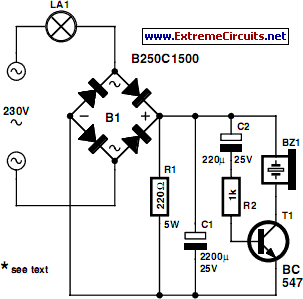
If a lamp incorporating a motion sensor is utilized for outdoor illumination, the original manual switch is generally no longer required. By replacing the switch with the circuit detailed herein, an audible signal will be produced each time the external lamp is activated. This arrangement falls somewhere between an alarm and a doorbell. The underlying principle is straightforward. A circuit designed to induce a voltage drop of only a couple of volts is connected in series with the lamp. Given that this circuit necessitates a direct current voltage, the current flowing through the lamp passes via a bridge rectifier.
The voltage drop across the circuit is determined by R1. The function of C1 is to smooth the raw direct current voltage. It’s important to note that this is not a scenario involving peak rectification, but instead one where the voltage is averaged. Consequently, the voltage held on C1 is lower than one might anticipate. Eventually, the direct current voltage on C1 reaches a value that matches the average voltage across R1. For instance, consider the situation when utilizing a 100-W lamp. For ease of calculation, we can assume the lamp possesses a resistance equivalent to 529 R. If we disregard the voltage across the diodes and the voltage across R1, the current is approximately 0.39 A on average (not 0.43 A).
This approximation is based on the average mains voltage of 207 V = (230 × v2) ÷ (p/2). This yields a voltage of approximately 8.5 V on C1. As the buzzer and T1 only draw a few milliampères from C1, in practice the voltage will deviate from this value by at most a few tenths of a volt. It is advisable to utilize a DC buzzer with a wide operating voltage range. A suitable example is the CEP-2260A, which possesses a voltage range of 3–20 V (available from Digi-Key and other online sources). The charging time of C2 dictates how prolonged the buzzer remains active, and it will typically be a few tenths of a second.
Circuit diagram
Depending on the current drawn by the buzzer, it may be necessary to increase the value of R2 in order to extend the duration of the signal (this is particularly crucial with the buzzer type mentioned above). Depending on the lamp’s power, adjustments to the value of R1 should be considered. This is certainly necessary if a 150-W lamp or a larger one is being used. In this case, the value of R1 should be halved, primarily due to the potential for excessive power dissipation, which would amount to approximately 3 watts. The bridge rectifier warrants particular attention.
A significant current can flow briefly when the lamp is initially switched on. A 250V, 1.5-A bridge rectifier is sufficient for a 100-W lamp, but more robust diodes are needed with higher lamp power – such as the 1N5408 (1000 V / 3 A). Because of the heat generated by R1, ensure that R1 is positioned a certain distance away from the other components in the assembled circuit. Furthermore, it must be remembered that the entire circuit is connected to mains potential. Never make any modifications while the circuit is connected to the mains! It’s thus beneficial to test the circuit prior to installing it into the switch box.
