- Build Your Inspiring 240VAC Mains Smoke Detector Alarm Circuit
- Build a Powerful 200mA Security Siren Circuit
- 3V Mini Alarm Circuit Diagram & Build Guide
- Laptop Alarm Circuit: Build Your Theft Protection Scheme
- DIY Motion-Activated Alarm Circuit with 100W Lamp
- 5-Digit Alarm Keypad: Build Your Secure Circuit Diagram
- Build Your 4-Digit Alarm Keypad Circuit Diagram
- Build Your 20-Minute Battery Burglar Alarm Schematic
- Enhanced Shed Alarm Circuit Diagram with 30-Second Delays
- Simple Fire Door Alarm Circuit Design & Timing Control
- Simple Shop Alarm: Build a 3-5 Second Beep Timer
- Four Transistor Alarm Circuits: Design & Build Your Own!
- 12 Small CMOS Alarm Circuits Diagrams – Build Your Own!
- Build Your 12V Burglar Alarm Circuit Diagram
- Build Your 30-Second Alarm: Circuit Diagram & Design
Enhanced Shed Alarm Circuit Diagram with 30-Second Delays
Description
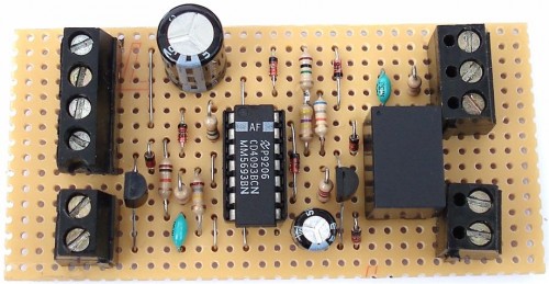
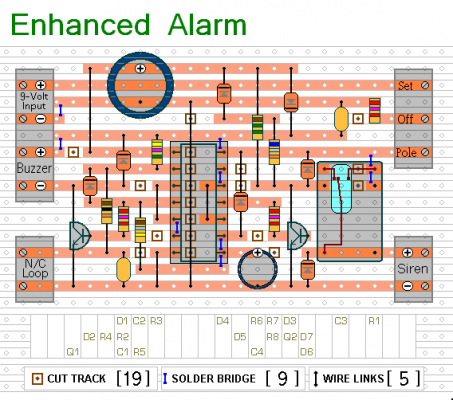
This revised iteration of the basic Garage/Shed Alarm incorporates several enhancements. The Entry and Exit delays have been extended to approximately 30 seconds, and a timed Siren cut-off alongside an automatic Reset function have been implemented. Furthermore, the LED has been replaced with an audible Buzzer. These modifications broaden the scope of application for this new version considerably.
The circuit is intended for utilization with conventional contact devices such as magnetic-reed contacts, miniature switches, foil tape, and Passive Infrared (PIR) sensors.
Although powered by mains electricity, the exceptionally low standby current makes it suitable for battery operation. A 9-volt battery is demonstrated in the diagram, however, the circuit operates effectively within a voltage range of 5 to 15 volts. Select a Relay, Buzzer, and Siren that aligns with your desired voltage level.
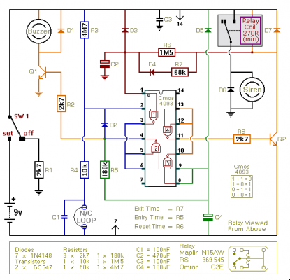
Schematic Diagram
To activate the alarm, move SW1 to the “set” position. You are then afforded approximately 30 seconds to vacate the building. Upon returning and opening the door, the Buzzer will initiate. Subsequently, you have another 30 seconds to reposition SW1 to the “off” position. Should this action not be taken within the allotted time, the relay will energize, and the Siren will sound.
After roughly 10 minutes, the alarm attempts to self-reset. If the triggering circuit has been restored, the reset will succeed. However, if the loop remains open, the attempt will fail, and the alarm will re-activate. The circuit will continue its automated reset attempts every five minutes thereafter, until the triggering circuit is restored or the alarm is manually switched off.
Should a 1M5 resistor not be available, a 1M and a 470k resistor connected in series can be utilized. This is the configuration I employed. Due to manufacturing variations, the precise duration of any delay is contingent on the characteristics of the specific components utilized in your circuit. Yet, adjusting the values of R5, R6, & R7 enables you to fine-tune the Entry, Reset, and Exit times to match your particular requirements. Increasing the values results in a longer time duration – conversely, decreasing them shortens the time.
The circuit functions optimally with a Cmos 4093. The Cmos 4093 represents the Schmidt-Trigger version of the 4011. Although its logic is identical to that of the 4011, a key distinction lies in the presence of “Hysteresis” in the 4093. While the 4011 will operate, the lack of hysteresis in the 4011 may compromise its performance.


