- Build Your Inspiring 240VAC Mains Smoke Detector Alarm Circuit
- Build a Powerful 200mA Security Siren Circuit
- 3V Mini Alarm Circuit Diagram & Build Guide
- Laptop Alarm Circuit: Build Your Theft Protection Scheme
- DIY Motion-Activated Alarm Circuit with 100W Lamp
- 5-Digit Alarm Keypad: Build Your Secure Circuit Diagram
- Build Your 4-Digit Alarm Keypad Circuit Diagram
- Build Your 20-Minute Battery Burglar Alarm Schematic
- Enhanced Shed Alarm Circuit Diagram with 30-Second Delays
- Simple Fire Door Alarm Circuit Design & Timing Control
- Simple Shop Alarm: Build a 3-5 Second Beep Timer
- Four Transistor Alarm Circuits: Design & Build Your Own!
- 12 Small CMOS Alarm Circuits Diagrams – Build Your Own!
- Build Your 12V Burglar Alarm Circuit Diagram
- Build Your 30-Second Alarm: Circuit Diagram & Design
Build Your 4-Digit Alarm Keypad Circuit Diagram
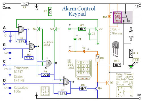
Schematic Diagram
Notes
The Keypad should be of the type featuring a single shared terminal alongside individual connections for each button. For a 12-button keypad, anticipate locating 13 terminals. Matrix-style keypads with 7 or 8 terminals are unsuitable. Detailed instructions on fabricating your own keypad can be found on the dedicated Support Page.
The relay receives power when a specific key is pressed. Select the desired key to activate the relay and connect it to terminal "E". Designate the four keys intended for your security code and connect them to "A B C & D". The common lead is connected to R1-, while the remaining keys are linked to “F”.
When “E” is pressed, the relay is energized, and the 12-volt output shifts from the "off" position to the "set" terminal. Additionally, the green LED illuminates, providing a visible signal that the alarm is active.
When keys “A B C & D” are pressed in the correct sequence, the relay disengages, and the 12-volt output returns to the "off" terminal. The green LED is extinguished, signifying that the alarm is deactivated.
The remaining keys - those not connected to "A B C D & E" - are connected to “F”. Any attempt to press one of these “Incorrect” keys will result in the code entry being canceled, and the sequence reset.
The identical outcome occurs if “C” or “D” is pressed out of order. If “C” is pressed prior to “B”, or “D” is pressed before “C”, the attempted code entry will fail, and the sequence will be reset.
With a 12-key keypad, over 10,000 unique codes are possible. For increased security, consider employing a larger keypad with more “Incorrect” keys wired to “F”. A 16-key keypad provides over 40,000 different codes. If a mistake occurs during code entry, simply begin the sequence anew.
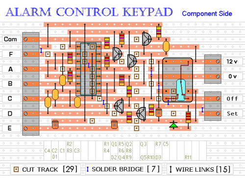
The supplementary materials for this circuit include a step-by-step guide to constructing the circuit board, a parts inventory, a comprehensive circuit diagram, and additional resources.

