- Build a 4-Stage Stabilised Power Supply with Short Circuit Protection
- Build Your Own 3-30V Adjustable DC Power Supply
- Build Your Own 9V 2A DC Power Supply Circuit
- Build Your Own: 1.3-22V Adjustable Power Supply Circuit
- Adjustable Current Limit: Dual Power Supply Design
- Build Your High-Performance 170V Hybrid Amplifier Power Supply
- Build Your 15V Regulated Power Supply Circuit – Simple & Powerful
- Transformerless 5V Power Supply Design Guide
- Build Your Own 24V 2A Variable DC Power Supply
- High Voltage Regulator: Design and Short Circuit Protection
- Boost Regulator Current: Design Your 1500mA Circuit
- Extend Smoke Alarm Battery Life with 12V Power
- 2 Watt Switching Power Supply: Build Your Own Circuit
- Variable Voltage & Current Power Supply: Build Your 0-3 Amp Circuit
- Build Your 24 Volt 3 Amp Power Supply Circuit
Variable Voltage & Current Power Supply: Build Your 0-3 Amp Circuit
Description
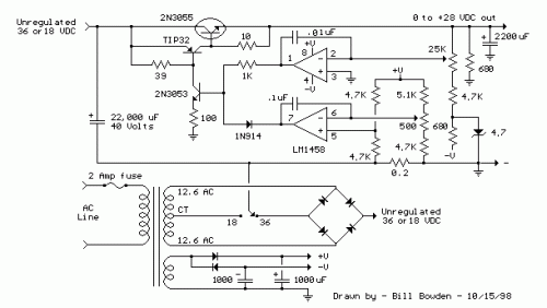
A method for utilizing op-amps in power supply regulation is illustrated below. The power transformer necessitates an additional winding to furnish the op-amps with a dual voltage supply (+/- 8 volts), and the negative voltage is also utilized to generate a reference voltage below ground, enabling the output voltage to be adjusted from its minimum value down to zero. Current limiting is achieved through sensing the voltage drop across a small resistor positioned in series with the negative supply line. As the current increases, the voltage at the wiper of the 500-ohm potentiometer rises until it equals or slightly exceeds the voltage at the (+) input of the op-amp. Subsequently, the op-amp output shifts negatively, reducing the voltage at the base of the 2N3053 transistor, which subsequently diminishes the current flowing through the 2N3055 pass transistor, maintaining the current at a constant level even with a shorted supply. The current limiting range is approximately 0 - 3 amps, utilizing the components shown. The TIP32 and 2N3055 pass transistors should be affixed to appropriate heat sinks, and the 0.2-ohm current sensing resistor should be rated for a minimum of 2 watts. The heat generated by the pass transistor is proportional to the difference between the input and output voltage, and the load current. For instance, if the input voltage (at the collector of the pass transistor) is 25 volts and the output is adjusted for 6 volts, while the load is drawing 1 amp, the heat dissipated by the pass transistor would be (25 - 6) * 1 = 19 watts. Switching the switch to the 18-volt position would reduce the heat generated to around 12 watts.
More about components
Integrated circuits (ICs) are complex electronic circuits miniaturized onto a single semiconductor chip. They consist of numerous transistors, diodes, and resistors interconnected to perform specific functions, such as amplification, switching, and logic operations. In this circuit, the 2N3053 and 2N3055 are examples of integrated circuits. The 2N3053 is a general-purpose NPN transistor, commonly utilized as a switching or amplification device. It’s a three-lead transistor featuring a collector, base, and emitter. The 2N3055 is also an NPN transistor, but it's specifically designed for power applications, providing higher current capability compared to the 2N3053. Both ICs are crucial for controlling the current flow within the circuit, enabling the regulation and limiting functionality. Selecting appropriate heat sinks for these integrated circuits is critical to prevent overheating and damage.
