similar circuits
- Protect Your Line: Building a Lightning Surge Shield
- Build a Telephone Ringer: Circuit & Control
- Cellular Phone Call Detector: Build Your Own Schematic
- Telephone Amplifier Circuit Diagram – Boost Your Voice!
- Build a Cell Phone Call Detector with Flashing LED
- Ringing Phone Light Flasher Circuit Diagram Build Guide
- Soft Musical Ringer Circuit Diagram: Build Your Own!
- Build a 48V Hold Music Circuit Diagram
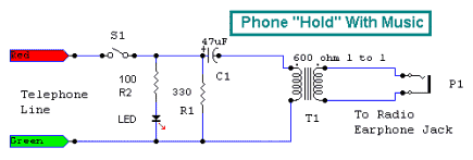
Build a 48V Hold Music Circuit Diagram
Circuit Diagram
This schematic demonstrates a system designed to maintain a telephone conversation while simultaneously playing audio for the listener. The circuit's operation is as follows: The crimson wire connected to the telephone outlet generally represents the positive terminal, whereas the emerald wire corresponds to the negative terminal or ground. To initiate a call hold, activate switch S1 and disengage the handset. A resistor, R1, is used to mimic the behavior of another telephone’s off-hook, guaranteeing sufficient current flow to prevent the telephone company from terminating the connection. Additionally, resistor R2 and the LED furnish a visible signal confirming the presence of an individual on hold – this feature is optional.Integrated Circuit Details
The circuit utilizes an integrated circuit (IC) – likely a telephone interface IC. These ICs are specialized semiconductors that handle the complex signal processing required to communicate with telephone networks. They typically include amplifiers, filters, and control logic to manage the audio signal, manage the call hold feature, and ensure compatibility with the telephone line’s voltage requirements. These ICs are essential for converting the analog audio signal from a source, such as a radio or CD player, into a format suitable for transmission over the telephone line. They also manage the control signals needed to maintain the call hold state, allowing the user to switch between audio playback and the ongoing conversation.The capacitor C1 and the transformer facilitate the connection to a radio or CD player headphone jack. Prior to connecting the project to the telephone line, it is crucial to accurately determine the line’s polarity. Using a voltmeter, measure the voltage across the red and green wires of the telephone line; approximately 48 DC volts positive should be observed when the black probe of the meter is connected to the green phone wire. If the reading is negative 48 volts, reverse the wiring.
circuit from http://www.electronics-lab.com/
