- Protect Your Line: Building a Lightning Surge Shield
- Build a Telephone Ringer: Circuit & Control
- Cellular Phone Call Detector: Build Your Own Schematic
- Telephone Amplifier Circuit Diagram – Boost Your Voice!
- Build a Cell Phone Call Detector with Flashing LED
- Ringing Phone Light Flasher Circuit Diagram Build Guide
- Soft Musical Ringer Circuit Diagram: Build Your Own!
- Build a 48V Hold Music Circuit Diagram
Ringing Phone Light Flasher Circuit Diagram Build Guide
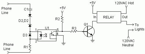
Several inquiries have been received regarding the connection of lighting devices to cause them to flash upon telephone ring detection. This configuration proves particularly valuable in environments characterized by significant ambient noise, rendering audible phone alerts impossible, such as within a workshop setting. The following circuit design provides a solution to this problem. The ring detection portion of this circuit was sourced from http://www.hut.fi/Misc/Electronics/circuits/telephone_ringer.html.
Circuit Diagram
Components:
- C1 0.47µF 250V Capacitor
- R1, R2 10kΩ 1/4 W Resistor
- R3 1kΩ 1/4 W Resistor
- D1, D2 20V 1/4 W Zener Diode
- D3 1N4148 Diode
- Q1 2N3904 NPN Transistor or 2N2222
- U1 4N27 Opto Isolator
- RELAY Solid State or Regular Relay (See Notes)
- MISC Case, Wire, Board
Notes:
- A lower voltage zener diode may be required for D1 and D2.
- A standard relay can be used in place of a solid-state relay; however, arcing across the contacts may quickly damage it.
- Absolute confirmation is necessary to ensure that no 120V power is inadvertently connected to the phone line during construction and installation.
Optoelectronic components play a crucial role in this design. The 4N27 optocoupler (U1) facilitates isolation between the phone line and the output stage, preventing ground loops and ensuring reliable operation. This isolation is fundamental for maintaining signal integrity in noisy environments. The 4N27 optocoupler is a dual-channel device, providing two independent channels for switching and isolation. It operates by converting electrical signals into light, which is then detected by a phototransistor. The phototransistor's output current is proportional to the incident light intensity, enabling controlled switching of the output stage. This allows the lighting circuit to be controlled without directly connecting to the phone line’s voltage.
