- Build Your Own 5V LED Tester with 30mA
- LED Tester Circuit Diagram for 3 LEDs
- DIY Continuity Tester Circuit: Build Your Own!
- Build Your Zener Diode Tester: Circuit & 25V Measurements
- Test Your Zener Diodes: 555 Timer Circuit for 1-2mA Loads
- Test Your 100KHz-30MHz Xtal Oscillator Circuit Diagram
- Build Your 12Hz Transistor Tester Circuit Diagram
- Mosfet Tester Circuit: Flash Test for N-Channel Devices
- Build Your Own Crystal Tester Circuit (32kHz-24MHz)
- Build Your Own PIC Diode Tester Circuit Diagram
Build Your Own PIC Diode Tester Circuit Diagram
This collection presents a straightforward application of the PIC 16F84 for a diode verification system.
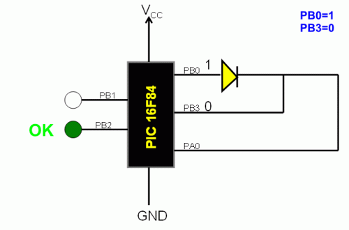
Circuit Diagram
The following test methodology is utilized: The digital input pins PB0 is configured with the value «1», while PB3 is set to «0». In the event that the diode functions correctly and provides an open circuit, a high signal («1») is observed on the output pin PA0. Conversely, if PA0 registers a value of «0», it indicates a fault within the diode. The programming controls the device’s response in each specific scenario. When PA0 is «1», a green LED illuminates, signifying a functional diode, and when PA0 is «0», a red LED activates, suggesting a defective diode. The continuous testing process involves setting PB0 to «0» and PB3 to «1». Similar to the previous test, a correct diode will result in a «1» signal on PA0, while a «0» signal on PA0 denotes a diode malfunction. The programming effectively manages the device's actions during each test state.
Integrated Circuit Details
PIC 16F84
The PIC16F84 is a versatile microcontroller unit manufactured by Microchip Technology. This integrated circuit is characterized by its 16-bit architecture, a substantial number of on-chip peripherals, and a robust Flash memory for program storage. It’s commonly used in embedded systems where real-time control and data acquisition are crucial. The 16F84 features a CPU clock speed, various timers, serial communication interfaces, and analog-to-digital converters. Its primary function here is to control the LED indicators and monitor the diode test signals, providing a user-friendly interface for testing diode functionality. It is a commonly used IC for controlling LEDs and reading input values from digital pins, making it a suitable choice for this diode testing application.
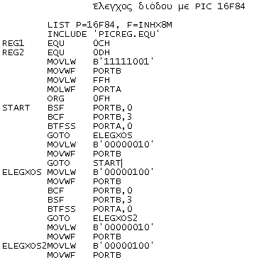
Source Code
circuit from http://www.electronics-lab.com/

