- Build Your Own 5V LED Tester with 30mA
- LED Tester Circuit Diagram for 3 LEDs
- DIY Continuity Tester Circuit: Build Your Own!
- Build Your Zener Diode Tester: Circuit & 25V Measurements
- Test Your Zener Diodes: 555 Timer Circuit for 1-2mA Loads
- Test Your 100KHz-30MHz Xtal Oscillator Circuit Diagram
- Build Your 12Hz Transistor Tester Circuit Diagram
- Mosfet Tester Circuit: Flash Test for N-Channel Devices
- Build Your Own Crystal Tester Circuit (32kHz-24MHz)
- Build Your Own PIC Diode Tester Circuit Diagram
Build Your Zener Diode Tester: Circuit & 25V Measurements
Circuit Diagram
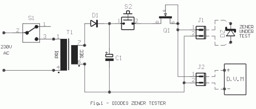
Frequently, the need arises to employ a Zener diode, yet its operating voltage remains unknown. Often, the stated characteristics or the printed type are unavailable. In this instance, but with a different approach, the circuit depicted in Figure 1 can be utilized. Components T1, D1, and C1 form a half-wave rectification system. Activating switch S2 allows a DC current to flow from the current limiter Q1 and the Zener diode DZ, which is assessed. Q1 ensures a stable current flow of 10mA regardless of the Zener voltage connected on connector J1. A digital voltmeter is connected to connector J2, enabling the observation of the voltage across Zener DZ. This circuit demonstrates dependable performance for measurements as low as 25Volts. A low voltage reading of 0.8Volts is likely attributable to the Zener diode DZ being connected in reverse polarity. Altering the polarity of the Zener diode DZ will resolve this issue.
Parts
Zener Diode
A Zener diode is a semiconductor device used for voltage regulation. It operates in reverse bias, maintaining a constant voltage across it when a specific current flows through it. The Zener diode DZ in this circuit provides a stable reference voltage, crucial for accurate measurements and circuit protection. The diode operates at a Zener voltage of 6.2V.
Current Limiting Resistor
The current-limiting resistor Q1 plays a vital role in the circuit. It restricts the current flowing through the Zener diode DZ to a safe and manageable level, typically 10mA. This protection is essential to prevent damage to the diode and ensure accurate voltage measurement. The resistor value is chosen based on the Zener diode's specifications and the desired current flow.
Capacitor
The capacitor C1 in the circuit serves as a filtering component, smoothing out the rectified DC voltage. It reduces the ripple effect, providing a more stable DC output. The capacitor's capacitance value of 1uF contributes to the overall stability of the circuit.
A warning regarding electrical safety should be observed when working with electronic circuits. Always disconnect the power supply before making any changes or modifications. Incorrect wiring or handling of electrical components can result in serious injury or damage to equipment. Furthermore, this circuit diagram is provided for educational purposes only. The author, [iName], acknowledges the source as [Source Name].
circuit from http://users.otenet.gr/~athsam/Diode_zener_tester.htm


