- Build Your Own 5V LED Tester with 30mA
- LED Tester Circuit Diagram for 3 LEDs
- DIY Continuity Tester Circuit: Build Your Own!
- Build Your Zener Diode Tester: Circuit & 25V Measurements
- Test Your Zener Diodes: 555 Timer Circuit for 1-2mA Loads
- Test Your 100KHz-30MHz Xtal Oscillator Circuit Diagram
- Build Your 12Hz Transistor Tester Circuit Diagram
- Mosfet Tester Circuit: Flash Test for N-Channel Devices
- Build Your Own Crystal Tester Circuit (32kHz-24MHz)
- Build Your Own PIC Diode Tester Circuit Diagram
Test Your 100KHz-30MHz Xtal Oscillator Circuit Diagram
Circuit diagram
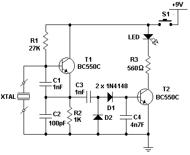
A straightforward XTal examination circuit is presented here. Transistor T1, in conjunction with the XTal, generates an oscillating signal. Capacitors C1 and C2 function as a voltage divider, establishing the parameters for the oscillation. Should the XTal operate correctly, the output voltage is subsequently smoothed by capacitors C3 and C4, followed by rectification performed by diodes D1 and D2. Consequently, transistor T2 is activated and the LED illuminates. This circuit is principally designed for evaluating Xtal frequencies within the range of 100KHz to 30MHz.
More about components
Integrated circuits, commonly known as ICs, are complex electronic circuits miniaturized onto a single semiconductor chip. These components are fundamental to modern electronic devices, providing compact and efficient solutions for various functions. In this particular circuit, the transistors T1 and T2 are examples of ICs. Transistors are semiconductor devices that control the flow of electric current, acting as switches or amplifiers. T1 and T2, likely bipolar junction transistors (BJTs), are utilized here to manage the oscillation and drive the LED. These ICs come in numerous forms and configurations, each tailored for specific applications. Their small size and integrated functionality significantly contribute to the reduction in circuit board space and improved reliability.
circuit from http://www.electronics-lab.com/
