- Build Your Own 5V LED Tester with 30mA
- LED Tester Circuit Diagram for 3 LEDs
- DIY Continuity Tester Circuit: Build Your Own!
- Build Your Zener Diode Tester: Circuit & 25V Measurements
- Test Your Zener Diodes: 555 Timer Circuit for 1-2mA Loads
- Test Your 100KHz-30MHz Xtal Oscillator Circuit Diagram
- Build Your 12Hz Transistor Tester Circuit Diagram
- Mosfet Tester Circuit: Flash Test for N-Channel Devices
- Build Your Own Crystal Tester Circuit (32kHz-24MHz)
- Build Your Own PIC Diode Tester Circuit Diagram
DIY Continuity Tester Circuit: Build Your Own!
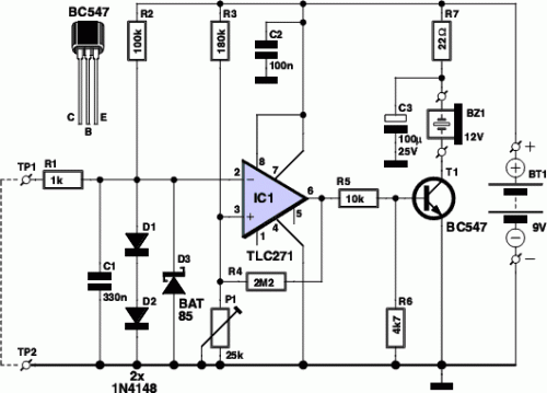
Circuit diagram:
Maintaining reliable contacts is crucial – not only in daily life, but also in electronics. Unlike social connections, the dependability of electrical contacts can be swiftly and easily verified. Numerous types of continuity testers are commercially available for this purpose. Most multimeters also include a continuity test function for electrical connections. A simple beep signals the distinction between good and poor connections.
However, in certain instances, the tester fails to produce a beep because it doesn’t accept contact resistances that are somewhat higher than usual. Also, connections that appear to be poorly conducting (and therefore bad) are sometimes reported as being good. Here, e-trix presents a design for a DIY continuity tester, which effectively separates the desirable from the undesirable.
Operational Amplifier (IC1) Description:
An operational amplifier, or op-amp, is a versatile integrated circuit used extensively in analog circuits. IC1, in this continuity tester, serves as a comparator. It efficiently compares two voltages, enabling the device to determine if a connection meets a specific resistance threshold. The op-amp's ability to amplify small voltage differences is fundamental to its operation, allowing the circuit to accurately detect even slight resistance variations. Its precision and stability are vital for achieving reliable contact testing.
Circuit description:
Many multimeters have a built-in continuity test function. However, in many instances, the resistance required to activate the beeper when searching for poor connections is just a little too high. It can also happen that the beeper sounds even though the resistance of the connection is unacceptably high. This circuit provides the ability to adjust the threshold between good and bad contacts to suit specific needs. The circuit is constructed around an operational amplifier (IC1) configured as a comparator.
The op-amp compares the voltage on its inverting input (pin 2) with the voltage on its non-inverting input (pin 3). The voltage on pin 3 can be adjusted using potentiometer P1, allowing the setting of the threshold between good and bad connections. When test probes TP1 and TP2 are placed on either side of a connection or contact to be tested, a voltage is generated across the probes by the current flowing through resistors R1 and R3, and it appears on pin 2 of the op-amp. This voltage depends on the resistance between the probe tips.
If the voltage on pin 2 is lower than the reference voltage on pin 3, the difference is amplified so powerfully by the op-amp that its output (pin 6) is essentially the same as the supply voltage. This causes transistor T1 to conduct, which in turn causes DC buzzer BZ1 to sound. This indicates that the resistance of the connection being tested is less than the threshold value set by P1, and therefore, the connection is satisfactory.
By contrast, a bad connection will cause the relationship between the voltages on the inputs of the op-amp to be the opposite, with the result that its output will be at ground level. The transistor will not conduct, and the buzzer will remain silent. To guarantee that the op-amp ‘switches’ properly (which means that its output goes to ground level or the supply voltage level) when the difference voltage is sufficiently large and does not oscillate during the transition interval due to small fluctuations in the difference voltage produced by interference, its output is coupled back to its non-inverting input (pin 3) by resistor R4.
This causes any change on the output to be passed back to this input in amplified form, with the result that the detected difference voltage is amplified (and thus boosted). Diodes D1, D2 and D3 protect the circuit against excessive positive and negative input voltages that may come from the connections or contacts being tested. They also ensure that the continuity tester does not inject excessively high voltages into the item under test. Capacitor C1 suppresses high-frequency interference. The circuit draws only a small supply current, so it can easily be powered by a 9-V battery.
