- Build Your Inspiring 240VAC Mains Smoke Detector Alarm Circuit
- Build a Powerful 200mA Security Siren Circuit
- 3V Mini Alarm Circuit Diagram & Build Guide
- Laptop Alarm Circuit: Build Your Theft Protection Scheme
- DIY Motion-Activated Alarm Circuit with 100W Lamp
- 5-Digit Alarm Keypad: Build Your Secure Circuit Diagram
- Build Your 4-Digit Alarm Keypad Circuit Diagram
- Build Your 20-Minute Battery Burglar Alarm Schematic
- Enhanced Shed Alarm Circuit Diagram with 30-Second Delays
- Simple Fire Door Alarm Circuit Design & Timing Control
- Simple Shop Alarm: Build a 3-5 Second Beep Timer
- Four Transistor Alarm Circuits: Design & Build Your Own!
- 12 Small CMOS Alarm Circuits Diagrams – Build Your Own!
- Build Your 12V Burglar Alarm Circuit Diagram
- Build Your 30-Second Alarm: Circuit Diagram & Design
Build Your Own 3V Personal Alarm Circuit Diagram
Portable, anti-theft protection unit
Also suitable for securing doors and windows
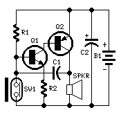
Circuit Diagram
Components:
- R1 330K 1/4W Resistor
- R2 100R 1/4W Resistor
- C1 10nF 63V Polyester or Ceramic Capacitor
- C2 100µF 25V Electrolytic Capacitor
- Q1 BC547 45V 100mA NPN Transistor
- Q2 BC327 45V 800mA PNP Transistor
- SW1 Reed Switch and small magnet (See Notes)
- SPKR 8 Ohm Loudspeaker (See Notes)
- B1 3V Battery (two A or AA cells wired in series etc.)
Device Purpose:
This circuit, housed within a small plastic enclosure, can be positioned inside a bag or handbag. A small magnet is positioned near the reed switch and connected to the person’s hand or clothing using a minuscule cord. Upon a sudden snatching attempt involving the bag, the magnet loses contact with the reed switch, SW1 disconnects, initiating an oscillating circuit and causing the loudspeaker to emit a loud warning sound. The device can be reversed, i.e., the enclosure can be placed in a pocket, and the cord connected to the bag. This apparatus proves valuable for signaling the opening of a door or window: the enclosure is placed on the frame, and the magnet on the movable part, ensuring close proximity when the door or window is closed.
Circuit Operation:
A complementary transistor pair is implemented as an efficient oscillator, directly powering a small loudspeaker. Its minimal component count and 3V battery power enable a highly compact construction.
Notes:
- The loudspeaker can be any type; its dimensions are limited solely by the box that will contain it.
- An on-off switch is unnecessary due to the low stand-by current draw, which is less than 20µA.
- Current consumption when the alarm is activated is approximately 100mA.
- If the circuit is utilized for anti-bag-snatching, SW1 can be replaced with a 3.5mm mono Jack socket and the magnet by a 3.5mm mono Jack plug with its internal wires joined. The Jack plug will be connected with the tiny cord etc.
- Voltage exceeding 4.5V should not be supplied to this circuit; it will not function, and Q2 could be damaged. A 3V power supply represents the best compromise in all cases.
Integrated Circuits (ICs) - Detailed Description
The BC547 and BC327 transistors are NPN and PNP bipolar junction transistors, respectively. These transistors act as switches and amplifiers within the circuit. The BC547 is a general-purpose transistor commonly used for switching and amplifying low-power signals, offering a gain of approximately 40 to 300, depending on the circuit configuration. It’s characterized by its moderate hFE (current gain) and relatively low collector-emitter saturation voltage, making it suitable for a variety of applications. The BC327 is a PNP transistor, offering similar characteristics to the BC547 but with reversed polarities. Its hFE value is generally lower than that of the BC547, and it’s often used in applications requiring a higher input impedance. Both transistors operate at 45V and can provide a current of 100mA or 800mA depending on the circuit configuration. Careful consideration of these parameters is crucial for optimal circuit performance and to prevent damage to the transistors.
