- Build Your Inspiring 240VAC Mains Smoke Detector Alarm Circuit
- Build a Powerful 200mA Security Siren Circuit
- 3V Mini Alarm Circuit Diagram & Build Guide
- Laptop Alarm Circuit: Build Your Theft Protection Scheme
- DIY Motion-Activated Alarm Circuit with 100W Lamp
- 5-Digit Alarm Keypad: Build Your Secure Circuit Diagram
- Build Your 4-Digit Alarm Keypad Circuit Diagram
- Build Your 20-Minute Battery Burglar Alarm Schematic
- Enhanced Shed Alarm Circuit Diagram with 30-Second Delays
- Simple Fire Door Alarm Circuit Design & Timing Control
- Simple Shop Alarm: Build a 3-5 Second Beep Timer
- Four Transistor Alarm Circuits: Design & Build Your Own!
- 12 Small CMOS Alarm Circuits Diagrams – Build Your Own!
- Build Your 12V Burglar Alarm Circuit Diagram
- Build Your 30-Second Alarm: Circuit Diagram & Design
Two-Zone Burglar Alarm Circuit Diagram & Timing Controls
Description
This is a dual-zone security system - incorporating automated exit, entry, and siren deactivation timers. It responds to typical normally-closed input devices, including magnetic reed contacts, foil tape, and passive infrared sensors (PIRs). A 12-volt power supply is utilized within this schematic, although the circuit functions effectively across a voltage range of 9 to 15 volts. Simply select a suitable siren, buzzer, and relay to match your desired voltage.
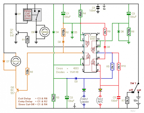
Schematic Diagram
Upon activation of Switch 1 in the ‘Set’ position, a thirty-second window is provided for egress from the building. Re-entry through the Exit/Entry zone triggers a buzzer activation, accompanied by a thirty-second delay before the alarm is deactivated. The Instant zone operates without any entry time restraint; entry via this zone immediately activates the siren.
Approximately ten minutes following the restoration of the normally-closed loops, the siren will disengage, and the system will return to its standby state. The alarm can then be reactivated in the event of subsequent intrusion. To prevent a second siren activation, incorporate the One-Time-Only Module. This module compels the siren to deactivate following the initial ten-minute period, effectively preventing any further alarm triggers. This module offers additional functionalities and warrants careful examination.
The various timing elements are detailed within the diagram. Modifying the length of any delays necessitates adjusting the value of the capacitor and/or the resistor depicted. An increase in either component's value extends the delay duration, while a decrease shortens it.
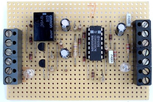
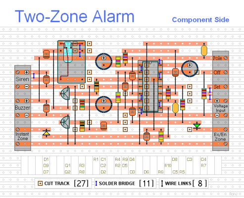
Stripboard Layout
More about components
This circuit utilizes several integrated circuits (ICs) to provide precise timing and control. The primary IC involved is a **Timer IC (e.g., NE555)**. This IC acts as a central timing element, generating the delays necessary for the alarm system's operation. The NE555 is a versatile IC commonly used in timer circuits due to its ability to generate accurate time delays based on capacitor and resistor values. It operates by switching between high and low states at a specific frequency determined by these components, creating the desired delay periods. The NE555's switching characteristics are crucial for achieving the precise timing required for the alarm’s various zones and functions.


