- Build Your Inspiring 240VAC Mains Smoke Detector Alarm Circuit
- Build a Powerful 200mA Security Siren Circuit
- 3V Mini Alarm Circuit Diagram & Build Guide
- Laptop Alarm Circuit: Build Your Theft Protection Scheme
- DIY Motion-Activated Alarm Circuit with 100W Lamp
- 5-Digit Alarm Keypad: Build Your Secure Circuit Diagram
- Build Your 4-Digit Alarm Keypad Circuit Diagram
- Build Your 20-Minute Battery Burglar Alarm Schematic
- Enhanced Shed Alarm Circuit Diagram with 30-Second Delays
- Simple Fire Door Alarm Circuit Design & Timing Control
- Simple Shop Alarm: Build a 3-5 Second Beep Timer
- Four Transistor Alarm Circuits: Design & Build Your Own!
- 12 Small CMOS Alarm Circuits Diagrams – Build Your Own!
- Build Your 12V Burglar Alarm Circuit Diagram
- Build Your 30-Second Alarm: Circuit Diagram & Design
Expandable Transistor Burglar Alarm Schematic Design
Description
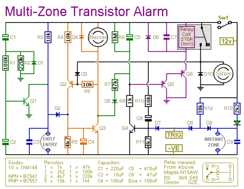
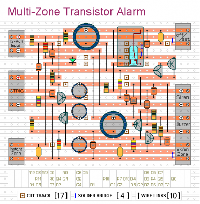
This is a straightforward transistor-based security system circuit. It incorporates automatic Exit and Entry delays, alongside a timed Bell cutoff and Reset function. It is intended for use with standard normally-closed input devices, such as magnetic-reed contacts, miniature switches, foil tape, and PIR sensors.
The fundamental alarm structure consists of an “Exit/Entry” area and an “Immediate” area. This arrangement is sufficient for numerous applications. Nevertheless, larger structures are optimally divided into several smaller zones. The alarm’s adaptable design allows for the addition of as many zones as needed to the system. These “Immediate” zones can be activated by either normally-open or normally-closed input devices.
More about components
The circuit utilizes the CD4010 – a versatile decade counter integrated circuit. This IC functions as a digital delay timer, enabling precise control over the alarm's delay periods. The CD4010 consists of four independent counting modules, each capable of counting from 0 to 9. The outputs of these modules are used to generate the delay times for the Exit/Entry and Instant zones. The IC’s pins are configured to provide the required timing signals for the alarm system. This IC is a common and reliable component widely used in timing applications due to its ease of use and readily available documentation.
Schematic Diagram
It’s easy to operate. Ensure the green LED illuminates, then activate the alarm using switch Sw1. You’re granted approximately 30 seconds to vacate the building. Upon your return and door opening, the Buzzer will sound. You are provided with roughly 30 seconds to deactivate the alarm. Failure to do so will trigger the Siren.
As long as at least one of the trigger switches remains open, the Siren will continue to sound. However, once the trigger circuits are restored, the alarm will reset itself after approximately 10 minutes. You can, of course, manually silence the Siren by turning off the alarm.
Due to manufacturing variations, the precise duration of any delay is contingent upon the characteristics of the actual components used in your circuit. However, by adjusting the values of R2, R7 & R9 – you can modify the Exit, Entry and Reset times to match your specific requirements. Increasing these values prolongs the time, and decreasing them shortens it.
If you do not desire the “Immediate” zone, omit D7, D8, D9, R12, R13, C8, and the Green LED.


