- Build Your Inspiring 240VAC Mains Smoke Detector Alarm Circuit
- Build a Powerful 200mA Security Siren Circuit
- 3V Mini Alarm Circuit Diagram & Build Guide
- Laptop Alarm Circuit: Build Your Theft Protection Scheme
- DIY Motion-Activated Alarm Circuit with 100W Lamp
- 5-Digit Alarm Keypad: Build Your Secure Circuit Diagram
- Build Your 4-Digit Alarm Keypad Circuit Diagram
- Build Your 20-Minute Battery Burglar Alarm Schematic
- Enhanced Shed Alarm Circuit Diagram with 30-Second Delays
- Simple Fire Door Alarm Circuit Design & Timing Control
- Simple Shop Alarm: Build a 3-5 Second Beep Timer
- Four Transistor Alarm Circuits: Design & Build Your Own!
- 12 Small CMOS Alarm Circuits Diagrams – Build Your Own!
- Build Your 12V Burglar Alarm Circuit Diagram
- Build Your 30-Second Alarm: Circuit Diagram & Design
Build Your Powerful Transistor Alarm Circuit Diagram
Description
This circuit incorporates automatic Exit and Entry delays – timed Bell/Siren cessation – and system reset functionality. It provides provisions for both normally-open and normally-closed switches and is suitable for all conventional input devices, including Pressure Mats, Magnetic Reed Contacts, Foil Tape, PIRs, and Inertia Sensors.
More about components
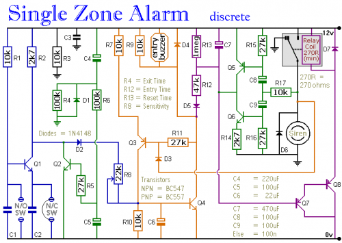
The core of this system relies on several integrated circuits for precise timing and control. Specifically, Q5 and Q6 are used as timer components, ensuring that the Entry and Siren Cut-off delays commence promptly upon restoration of the trigger circuit. These ICs function as precision oscillators, generating the necessary signals to manage the timing intervals. They are essential for maintaining the system’s responsiveness and reliability. These ICs are designed for stable operation and are commonly used in timer circuits due to their low power consumption and accurate timing characteristics.
Furthermore, D3 serves as a reset switch, effectively initiating the entire timing sequence when activated. This allows the system to return to its initial state, clearing any previous alarms and preparing for subsequent operations. The integrated circuit’s role is crucial in ensuring the system’s proper functioning and preventing unintended activations. Its design prioritizes quick and reliable resetting, providing a safety net in case of malfunctions or unexpected events. This component guarantees a clean restart, eliminating any potential errors and maintaining system integrity.
The system also utilizes Q5 and Q6, which act as timer components, managing the Entry and Siren Cut-off delays. These ICs operate by generating precise timing signals, ensuring the delays begin immediately when the trigger circuit is restored. They contribute to the system’s overall accuracy and responsiveness. The ICs are selected for their low power consumption and ability to provide stable timing, contributing to the system’s efficiency and reliability. They are commonly found in timer circuits and are essential for maintaining accurate timing intervals.
Finally, the system employs D3 as a reset switch, which initiates the entire timing sequence upon activation. This allows the system to revert to its initial state, clearing any previous alarms and preparing for subsequent operations. The integrated circuit’s function is vital in guaranteeing the system’s proper operation and preventing unintentional activations. Its design prioritizes a quick and dependable resetting process, providing a safety measure in situations involving malfunctions or unforeseen occurrences. This component ensures a clean restart, eliminating any potential problems and maintaining the integrity of the system.
The Exit delay, Entry delay, and Cut-off times can be adjusted by modifying the values of R4, R12, and R13, respectively. Q5 and Q6 are responsible for guaranteeing that the Entry delay and Siren Cut-off timers always begin with C7 either fully charged or fully discharged as required. If slight variations in time intervals are acceptable, omitting Q5, Q6, R14, R15, R16, R17, C8, and C9 will suffice. If the Siren’s cutoff should be disabled entirely, removing D3 is also necessary.
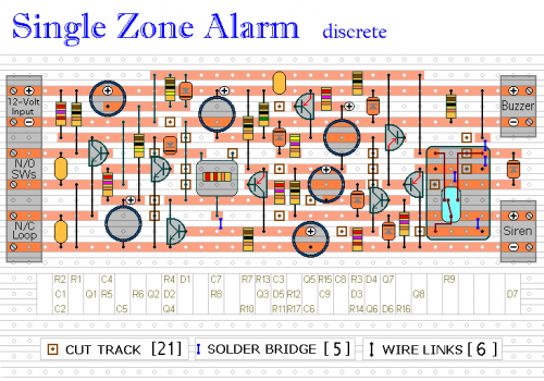
The sensitivity of the Inertia Sensors is governed by R8. Setting it to its minimum value triggers the alarm with a gentle tap. Conversely, setting it to its maximum value necessitates a substantial blow. If Inertia Sensors are not utilized, replacing R8 with a 27k fixed resistor is recommended. If normally-open switches are not implemented, removing R1, C1, and Q1 is necessary, alongside fitting a link between R2 and C2.
Schematic Diagram
If the building is not secure – the Buzzer will sound when you switch on the alarm. In this circumstance, it should be turned off and an open window or door checked. If all the trigger switches remain intact, switching on the alarm will not cause the Buzzer to sound. Instead, the automatic Exit delay will initiate.
Approximately 30 seconds will be available to leave the building and close the door. Upon returning and opening the door, the Buzzer will sound. Then, another 30 seconds will be provided to deactivate the alarm. Failure to do so will result in the Siren sounding.
The maximum duration the Siren will sound is not fixed. The cut-off timer begins running only when the trigger circuit is restored. As long as a normally-closed switch remains open or a normally-open switch remains closed, the Siren will continue to sound.
To set the Siren to switch off after 10 minutes, a simple modification to the trigger circuit is required. The Cut-off timer will then begin running immediately upon alarm activation, and the Siren will cease sounding after 10 minutes, regardless of the trigger switch status.
The Exit delay, Entry delay, and Cut-off times can be adjusted by altering the values of R4, R12, and R13, respectively. Q5 and Q6 ensure that the Entry delay and Siren Cut-off timers always start with C7 either fully charged or fully discharged as required. If slight variations in time intervals are acceptable, omitting Q5, Q6, R14, R15, R16, R17, C8 & C9 will suffice. If you don’t want the Siren to Cut-off at all - then leave out D3 as well.
The sensitivity of the Inertia Sensors is adjusted by R8. Set to minimum value - a light tap will activate the alarm. Set to maximum value - a heavy blow is required. If you are not using Inertia Sensors - replace R8 with a 27k fixed resistor. If you are not using normally-open switches - leave out R1, C1 & Q1 - and fit a link between R2 and C2.


