similar circuits
- Simple 4 Transistor Hearing Aid Circuit Diagram
- Amplified Ear: Build a Sensitive Sound Amplifier
- Build Your Own 3V Hearing Aid Circuit Diagram
- Studio Stereo Headphone Amplifier Circuit Diagram
- Stereo Headphone Amplifier: Build Your 90mR Circuit
- 427mW Class-A Headphone Amp
- Portable Headphone Amp: Circuit & 3.7V Upgrade
- 100mW Headphone Amplifier Schematic Build Guide
- LME49830 High Power Amplifier Circuit Diagram
- TDA7052 Speech Amplifier Circuit Diagram & Build Guide
- DC-Coupled Audio Amplifier Design: A Practical Guide
- Build a Low-Power IR Audio Amplifier Circuit Diagram
- 8 Watt Audio Amplifier Schematic: Build Your Powerful Project
- 7 Watt TDA2003 Audio Amplifier Circuit Design
- High-Power 60W Audio Amplifier Schematic Design
8 Watt Audio Amplifier Schematic: Build Your Powerful Project
Description
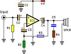
The following schematic illustrates a design for a 8-watt audio power amplifier. This device is suitable for a straightforward amplification task, forming the core element of a more complex amplifier system, or utilized as a guitar amplifier. It represents a compact and mobile unit, capable of operation through a 12V battery supply. The circuit was developed on a Vero Board, necessitating supplementary inductors, capacitors, and resistors to mitigate any potential oscillations.
Circuit diagram:
Parts:
- R1 = 47K
- R2 = 2.2R/1W
- R3 = 220R/1W
- R4 = 2.2R/1W
- C1 = 100nF-63V
- C2 = 10uF-25V
- C3 = 470uF-25V
- C4 = 2000uF-25V
- C5 = 100nF-63V
- IC1 = LM383
- SPKR = 4ohm/8W
Notes:
- IC1 has to be mounted on a heat sink for proper functionality.
- C1 serves for filtering purposes and preventing oscillations; its omission is discouraged.
- The circuit can be constructed on a Vero Board, a universal solder board, or a printed circuit board; a printed circuit board is generally preferred.
- The circuit consumes approximately 880mA at a 12V supply.
- By changing the values of R2 and R3, it is possible to transform this amplifier into a guitar amplifier without the need for a preamplifier.
- If a 2200uF capacitor is unavailable, a suitable replacement with a 2000uF unit can be used.
- The inclusion of a 0.2uF capacitor in series with a 1 ohm resistor at the output can effectively mitigate oscillation under specific conditions.
