- Simple 4 Transistor Hearing Aid Circuit Diagram
- Amplified Ear: Build a Sensitive Sound Amplifier
- Build Your Own 3V Hearing Aid Circuit Diagram
- Studio Stereo Headphone Amplifier Circuit Diagram
- Stereo Headphone Amplifier: Build Your 90mR Circuit
- 427mW Class-A Headphone Amp
- Portable Headphone Amp: Circuit & 3.7V Upgrade
- 100mW Headphone Amplifier Schematic Build Guide
- LME49830 High Power Amplifier Circuit Diagram
- TDA7052 Speech Amplifier Circuit Diagram & Build Guide
- DC-Coupled Audio Amplifier Design: A Practical Guide
- Build a Low-Power IR Audio Amplifier Circuit Diagram
- 8 Watt Audio Amplifier Schematic: Build Your Powerful Project
- 7 Watt TDA2003 Audio Amplifier Circuit Design
- High-Power 60W Audio Amplifier Schematic Design
Stereo Headphone Amplifier: Build Your 90mR Circuit
Description
It is important to note that the intended application of this circuit is just one possibility among many. Besides its obvious use as a headphone amplifier, the circuit can be employed in a variety of scenarios where a wide bandwidth, low-power amplifier is required. The circuit’s design utilizes an operational amplifier, with its output current amplified by a pair of transistors.
The appropriate value for the bias diodes should be 1N914 or a similar type – standard power diodes are not recommended, as their forward voltage drop is too low. This can potentially cause distortion within the crossover region, where one transistor transitions between on and off states. The concept for this circuit is credited to SiliconChip.
TL072 Operational Amplifier
The TL072 is a versatile operational amplifier known for its low input bias current, low input offset current, and high open-loop gain. It’s a popular choice for audio circuits due to its excellent noise performance and stability. Its characteristics make it suitable for applications requiring precise amplification and minimal distortion. It’s a JFET-input op-amp, which contributes to its low noise performance. Its primary function is to amplify the signal received from the input socket and drive the output transistors. It’s crucial for maintaining a stable and accurate amplification of the audio signal.
BC338 and BC328 Transistors
BC338 and BC328 are NPN bipolar junction transistors frequently used in amplifier circuits. BC338 is a general-purpose transistor, commonly employed in low-power audio applications, while BC328 is another general-purpose transistor with similar characteristics. These transistors play a vital role in boosting the output current of the op-amp, ensuring sufficient power is delivered to the headphones. The current gain of these transistors is critical in determining the amplifier’s output power.
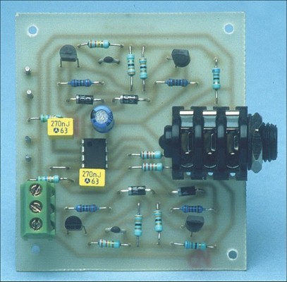
Picture of the circuit:
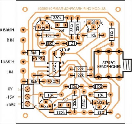
Parts layout:
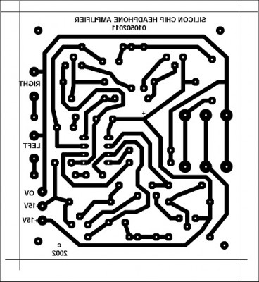
PCB layout:
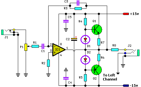
Circuit diagram:
Parts List:
- P1 = 50K
- R1 = 56K
- R2 = 22K
- R3 = 330K
- R4 = 10K
- R5 = 10K
- R6 = 33R
- R7 = 33R
- R8 = 68R
- C1 = 0.27uF
- C2 = 10uF-35V
- C3 = 5pF
- C4 = 100nF-63V
- C5 = 100nF-63V
- D1 = 1N914
- D2 = 1N914
- Q1 = BC338
- Q2 = BC328
- IC1 = TL072
- J1 = Audio Input Socket
- J2 = Stereo Headphone Socket
Performance of Prototype:
- Output level == 90mR (max) into 8W headphones
- Input sensitivity == 0.83V RMS for full power
- Frequency response == 0.5dB down at 30Hz and 20kHz
- Signal-to-noise ratio == -95dB unweighted (20Hz to 20kHz) with respect to 500mV input signal
- Separation between channels = = -50dB between 20Hz and 10kHz


