- Build Your Perfect Paraphase Tone Control
- Digital Volume Control Circuit Diagram – Build Your Own!
- Automatic Loudness Control Circuit: Design & Implementation
- Build Your 10-Band Graphic Equalizer Circuit
- Build Your Own 6-Band Graphic Equalizer Circuit
- Build Your 5-Band Graphic Equalizer Circuit
- Build Your 3-Band Equalizer Circuit (TL072)
- Build Your Perfect Parametric Mid-Range Equalizer Circuit
- Auto Fade Voice Amplifier Circuit Design
- Build Your Own Stereo Preamplifier: TCA5500 Circuit Diagram
- Automatic Loudness Control Circuit Diagram – Build Your Ideal Sound
- Build Your 1669 Digital Volume Control Circuit
- Build Your Classic Tone: LM1036 Circuit Diagram
Auto Fade Voice Amplifier Circuit Design
Description
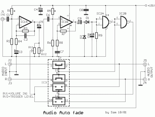
This circuit is designed to amplify the voice above music. It’s useful for DJs, small radio stations, announcements in shops, and other applications requiring voice amplification. It can handle stereo music and monophonic microphone signals, although modifications are possible to adapt it to specific needs and usage scenarios. The anticipated power supply is a single +15V, but a symmetrical ±9V from two batteries can also be used, producing ±15V. In this configuration, the resistances R1 through R5 are removed, and pin 4 of IC1 is connected to the negative voltage, while the other pins remain as they are. IC1A constitutes an amplifier that strengthens the microphone signal; it can be modified to adjust the gain rate to match the desired level. The acoustic signal branch is then routed through the potentiometer RV1, which regulates the sound intensity, applied to the two switches of IC3, in pins 9 and 10, with a resistance of approximately 10MΩ when not energized. When energized, this resistance drops to approximately 300Ω, allowing the signal to pass through. Similarly, this effect applies to the remaining switches comprising IC3. Via RV2 and IC2β, another amplifier further strengthens the signal, ultimately rectified by D1-2, C10 and R9, providing a pulsed DC signal synchronized with the IN1 signal, which controls the switching state of IC2A and IC2B. In a quiescent state, the outputs of IC2A-IC2B exhibit high rates at the 3rd position and a low rate at the 4th. Thus, switches IC3α and IC3β are in the ON (closed) position, allowing the stereo signal to pass through. When sound excitation is present at entry J1, as described above, the states of IC2A-IC2B change, influencing the state of switches IC3A-B, opening (OFF) IC3A-B and closing (ON) IC3C-D, reversing the previous configuration. This interrupts the stereo signal and allows the signal flow from J1. To test the circuit, a musical program is typically placed in entries J2-3, which passes through exits J4-5 without reduction or distortion for both channels. A microphone is connected to entry J1, RV2 is adjusted to its extreme position, and it’s slowly turned on until the microphone signal passes through. Upon completion of speech, the circuit may vibrate. If this occurs, RV2 likely has a high resistance. Through experimentation with the gain of IC1A-B and the adjustment of RV2, the desired output can be achieved. If a different signal source is used at entry J1, a new regulation will be required.
Circuit diagram
Part list
- R1-2= 1Mohms
- R5-6= 1Mohms
- R5-6= 1Mohms
- R3= 150Kohms
- R4-8= 1Kohms
- R7= 220Kohms
- R9= 470Kohms
- C1-6= 220nF 100V MKT
- C2= 100pF ceramic
- C3= 1uF 25V
- C4= 47uF 25V
- C5= 10uF 25V
- C7-8= 100nF 100V MKT
- C9-10= 4.7uF 25V
- D1-2= 1N4148
- IC1= TL072
- IC2= 4011
- IC3= 4016 - 4066
- J1-2= RCA Famale Plung
- RV1= 47Kohms Log. pot.
- RV2= 47Kohms Lin. pot.
- All Resistors is 1/4W 1-5%
Integrated Circuits Descriptions
IC1 (TL072) is a dual operational amplifier. Operational amplifiers are high-gain, differential amplifiers. The TL072 is a low-noise, JFET-input operational amplifier, commonly used in audio applications due to its low distortion and noise characteristics. It is ideal for amplifying weak signals and building precision amplifiers. It’s typically used for audio buffering, preamplification, and active filtering.
IC2 (4011) is a CMOS Decade Counter. Decade counters are integrated circuits that count from 0 to 9. The 4011 is a versatile IC that can be used for many purposes, including as a digital delay or timing circuit. It’s known for its low power consumption and high input impedance. This specific IC is typically used in timing circuits, digital displays, or as a building block in more complex digital systems.
IC3 (4016 – 4066) is a logic gate IC. These ICs consist of various logic gates, such as AND, OR, NOT, NAND, NOR, and XOR. The 4016 and 4066 are common versions that contain a mix of these gates. These ICs are used in digital circuits to implement logic functions. They are fundamental building blocks in digital electronics and are frequently used in control systems, digital displays, and other logic-based circuits. The specific arrangement of gates will dictate the functionality of the circuit.
