- Build Your Perfect Paraphase Tone Control
- Digital Volume Control Circuit Diagram – Build Your Own!
- Automatic Loudness Control Circuit: Design & Implementation
- Build Your 10-Band Graphic Equalizer Circuit
- Build Your Own 6-Band Graphic Equalizer Circuit
- Build Your 5-Band Graphic Equalizer Circuit
- Build Your 3-Band Equalizer Circuit (TL072)
- Build Your Perfect Parametric Mid-Range Equalizer Circuit
- Auto Fade Voice Amplifier Circuit Design
- Build Your Own Stereo Preamplifier: TCA5500 Circuit Diagram
- Automatic Loudness Control Circuit Diagram – Build Your Ideal Sound
- Build Your 1669 Digital Volume Control Circuit
- Build Your Classic Tone: LM1036 Circuit Diagram
Automatic Loudness Control Circuit Diagram – Build Your Ideal Sound
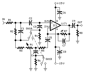
Circuit diagram:
Parts:
- P1 10K Linear Potentiometer (Dual-gang for stereo)
- R1,R6,R8 100K 1/4W Resistors
- R2 27K 1/4W Resistor
- R3,R5 1K 1/4W Resistors
- R4 1M 1/4W Resistor
- R7 20K 1/2W Trimmer Cermet
- C1 100nF 63V Polyester Capacitor
- C2 47nF 63V Polyester Capacitor
- C3 470nF 63V Polyester Capacitor
- C4 15nF 63V Polyester Capacitor
- C5,C9 1µF 63V Electrolytic or Polyester Capacitors
- C6,C8 47µF 63V Electrolytic Capacitors
- C7 100pF 63V Ceramic Capacitor
- IC1 TL072 Dual BIFET Op-Amp
Comments:
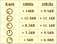
To achieve optimal audio reproduction across a range of listening volumes, adjusting the tone-control settings is necessary to align with the inherent, non-linear sensitivity of the human ear. The human auditory system exhibits variable sensitivity throughout the entire audible frequency spectrum, as depicted by the Fletcher-Munson curves. A straightforward solution involves incorporating a circuit into the preamplifier stage that automatically modulates the frequency response of the entire audio chain in relation to the control knob position, ensuring ideal listening conditions at differing volume levels. Fortunately, the human ear isn't overly critical, and a relatively simple circuit can furnish satisfactory performance within a 40dB range. The depicted circuit is presented with SW1 in the "Control-flat" position, meaning without Automatic Loudness Control. In this configuration, the circuit functions as a linear preamplifier stage, with the voltage gain determined via Trimmer R7. Shifting SW1 to the alternative position transforms the circuit into an Automatic Loudness Control, and its frequency response varies relative to the control knob position, as detailed in the table below. C1 strengthens the low frequencies, while C4 amplifies the higher frequencies. The maximum boost at low frequencies is constrained by R2, and R5 performs a similar function at high frequencies.
Technical data:
Frequency response referred to 1KHz and various control knob positions:
Total harmonic distortion at all frequencies and 1V RMS output: < 0.01%
Notes:
- SW1 is shown in "Control flat" position.
- The schematic illustrates only the left channel; therefore, for stereo operation, all components, excluding IC1, C6, and C8, must be duplicated.
- The numbers in parentheses indicate the pin connections for the IC1 right channel.
- Trimmer R7 should be calibrated to maximize undistorted output power when utilizing a standard music source and P1 rotated fully clockwise.
IC1 TL072 Dual BIFET Op-Amp
The TL072 is a dual operational amplifier IC offered by Texas Instruments. It's a low-noise, rail-to-rail input operational amplifier that is commonly used in audio applications due to its low input bias current and high open-loop gain. It's a versatile component suitable for a wide variety of amplification and filtering circuits. Its JFET input transistors provide high input impedance, minimizing loading effects on the signal source. The device is supplied with a fixed supply voltage and has a wide operating temperature range.
circuit from http://www.redcircuits.com/

