- Build Your Perfect Paraphase Tone Control
- Digital Volume Control Circuit Diagram – Build Your Own!
- Automatic Loudness Control Circuit: Design & Implementation
- Build Your 10-Band Graphic Equalizer Circuit
- Build Your Own 6-Band Graphic Equalizer Circuit
- Build Your 5-Band Graphic Equalizer Circuit
- Build Your 3-Band Equalizer Circuit (TL072)
- Build Your Perfect Parametric Mid-Range Equalizer Circuit
- Auto Fade Voice Amplifier Circuit Design
- Build Your Own Stereo Preamplifier: TCA5500 Circuit Diagram
- Automatic Loudness Control Circuit Diagram – Build Your Ideal Sound
- Build Your 1669 Digital Volume Control Circuit
- Build Your Classic Tone: LM1036 Circuit Diagram
Build Your 5-Band Graphic Equalizer Circuit
Description
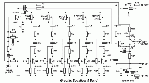
An additional graphic equalizer unit has been developed. This five-band equalizer distinguishes itself from other designs by utilizing transistors instead of integrated circuits and a power supply delivering a voltage range of +/- 24V DC. This configuration guarantees minimal distortion and expanded overload protection capabilities. Employing switch S1 facilitates isolating the equalizer, allowing the audio signal to pass through unaltered, either within or outside the equalizer’s operational mode.
Transistors
The core of this equalizer's functionality relies on seven BC550C transistors. These NPN bipolar junction transistors are commonly employed as switching and amplification devices. They contribute to the signal shaping and overall performance of the graphic equalizer. BC550C transistors are general-purpose devices, known for their reliability and moderate gain characteristics, suitable for a wide range of audio applications. Their use results in a greater headroom and reduced noise compared to IC solutions.
Circuit diagram
Part list
- R1-4-37= 330Kohms
- R2-7= 2.2Kohms
- R3= 120Kohms
- R5-6= 6.8Kohms
- R8....12= 1.8Kohms
- R13....15= 200Kohms
- R16= 180Kohms
- R17= 150Kohms
- R18= 1.5Kohms
- R19....22= 1Kohms
- R23....27= 220Kohms
- R28....32= 15Kohms
- R33= 10Kohms
- R34= 15Mohm
- R35-38= 220 ohms 1W
- R36= 100 ohms
- C1-3= 1uF 40V
- C2= 68pF 100V
- C4= 220uF 63V
- C5= 1uF 100V
- C6= 220nF 100V
- C7= 47nF 100V
- C8= 15nF 100V
- C9= 5.6nF 100V
- C10= 47nF 100V
- C11= 15nF 100V
- C12= 4.7nF 100V
- C13= 1.5nF 100V
- C14= 470pF 100V
- C15= 68pF 100V
- C16-19= 100nF 100V
- C17-20= 470uF 40V
- C18= 4.7uF 63V
- RV1....5= 50Kohms Lin.
- Q1.....7= BC550C
- S1= 2X2 SW
