- Build Your Perfect Paraphase Tone Control
- Digital Volume Control Circuit Diagram – Build Your Own!
- Automatic Loudness Control Circuit: Design & Implementation
- Build Your 10-Band Graphic Equalizer Circuit
- Build Your Own 6-Band Graphic Equalizer Circuit
- Build Your 5-Band Graphic Equalizer Circuit
- Build Your 3-Band Equalizer Circuit (TL072)
- Build Your Perfect Parametric Mid-Range Equalizer Circuit
- Auto Fade Voice Amplifier Circuit Design
- Build Your Own Stereo Preamplifier: TCA5500 Circuit Diagram
- Automatic Loudness Control Circuit Diagram – Build Your Ideal Sound
- Build Your 1669 Digital Volume Control Circuit
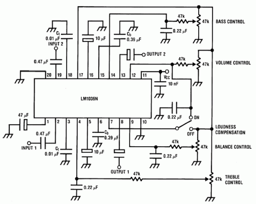
- Build Your Classic Tone: LM1036 Circuit Diagram
Build Your Classic Tone: LM1036 Circuit Diagram
Circuit diagram
The LM1036 is a direct current regulated tone (bass/treble), volume and balance circuit intended for stereo applications within car radios, televisions, and audio systems. An extra control input enables straightforward adjustment of loudness. Four control inputs manage the bass, treble, balance, and volume functionalities by applying DC voltages from a distant control system or, alternatively, via four potentiometers powered by a zener-regulated supply.
Integrated Circuit Details
The LM1036 utilizes a specific integrated circuit to achieve its tonal control functions. This IC is a versatile audio amplifier chip designed for low-noise signal processing and amplification. It typically contains several internal amplifier stages and filter networks, meticulously designed to deliver precise audio output. Its core functionality involves receiving an input audio signal, amplifying it, and shaping the frequency response through internal filter circuitry. The IC's architecture includes precision resistors and capacitors to accurately control gain and filter characteristics, ensuring accurate bass and treble tone adjustment. It's crucial to note that the LM1036's performance depends heavily on the correct selection and placement of external components, particularly the output capacitors, to optimize signal integrity and minimize noise.
Features:
- A broad operating power supply range, spanning 9V to 16V
- An extensive volume control range, approximately 75 dB
- Tone control capabilities, exhibiting a typical ±15 dB variation
- Channel separation of 75 dB
- Low distortion levels, a typical value of 0.06% at an input level of 0.3 Vrms
- High signal-to-noise ratio, reaching 80 dB at an input level of 0.3 Vrms
- A relatively small number of external components are needed
Note:
The supply voltage can be situated anywhere between 9V and 16V, and the output capacitors are 10uF/25V electrolytic
circuit from http://www.electronics-lab.com/
