- Relay Control with Logic Levels: Resistor Guide
- Monostable Flip Flop Circuit: Build Your Timing Delay
- Bistable Flip Flop Circuit: Build Your Stable Electronic Switch
- Set/Reset Flip Flop: Build Your 1-Bit Memory Circuit
- Build Your Own 4017 LED Traffic Light Circuit Diagram
- Build Your 7490 Frequency Divider: A Powerful 2-10 Circuit
- Frequency Doubler: Build Your 4011 Circuit Diagram
- Build a 4069 Frequency Doubler Circuit Diagram
- Build a 50Hz to 25Hz Frequency Divider Circuit
- Build Your Classic MM5314N Digital Clock Circuit
- Step Km Counter Circuit Design
- Build Your 7 Segment LED Counter with a 74LS90
- Build Your Pocket Distance Counter!
Build Your Classic MM5314N Digital Clock Circuit
Description
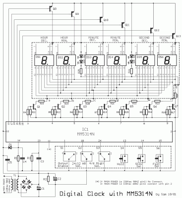
The digital timepiece circuit, utilizes one IC, the MM5314N, within which are contained all the necessary circuits. The IC1 collaborates with six displays of common anode, which are not critically dependent on materials. You can select the desired dimension, it is enough to adapt the pins accordingly within the circuit. The displays are driven by a system of polyplexes and are driven by thirteen transistors. For timing the circuit, the frequency of the network (50HZ) is employed. This solution represents the simplest approach, though it is not the most precise. For a more consistent frequency, a circuit based on a crystal could be implemented (this will be addressed shortly). The indication of the hour is provided by six displays of seven elements common anode. The DS1-DS2, display the hours (decades-unit respectively), the DS3-DS4, display the minutes and DS5-DS6, the seconds. The common anode, for each display, is driven by the collector of transistors Q8 through Q13. Individual LEDs (a, b, c, d, e, f, g) illuminate the display, they are linked in parallel and are driven by the transistors Q1 through Q7, thus creating a system of multiplexing with a frequency of 1KHZ, determined by the R3-C3. The power supply is a classic circuit, based on T1 and GR1, C1. The remaining capacitors, such as C2-C5 and R5, provide local decoupling of voltage and protect the IC1 from voltage spikes. The diode D1, limits the peak value of the rectified vibrations at pin 16. Resistances R18 through 24, limit the current leakage of the LEDs. With switch S1 in place 2, the clock measures the time and the display remains open, with S1 in place 1, the display remains closed, and the clock continues working. This operation allows for the clock to be used in spaces where the display lighting is undesirable. With S2 in place 1, we have measurement in a 12-hour base while in place 2, we have measurement in a 24-hour base. With S3 in place 1, we see the measurement in seconds, while in place 2, we only see the measurement in hours and minutes, while the seconds do not function. With switches S4, S5, S6, we regulate the hour when there are interruptions in the operation of the clock, and it becomes the classic way that becomes in this type the clocks. The pin 11 [5060 of HZ Select] is the input with which we select the operation of MM5314N in main voltage frequency 60HZ or 50HZ. When we have main voltage 110Vac- 60HZ [USA system] then the pin 11 is connected in Vss @pin 2. If the main voltage is 220Vac - 50HZ [Europe system] the pin 11 is not connected anywhere, it remains that is to say in air. Pin 16 [5060 input], is the input, where is applied sample from the main voltage [50HZ or 60HZ]. With this sample function the counter circuits and become the measurement of time. Thus, if you have 220Vac/50HZ, then the pin 11 remains void. If you have 110V/60HZ, then the pin 11 it's connected in Vss @ pin 2.
Notice:
The MM5314N rather been withdrawn from the manufacture, likely it exists somewhere in small quantities. I don’t have anybody information around he.
Circuit diagram
Part list
- R1= 100Kohms
- R2= 47Kohms
- R3= 100Kohms
- R4.....10= 2.2Kohms
- R11.....17= 10Kohms
- R18.....24-25-26= 220 ohms 0W5
- R25-26=1.2Kohms 0W5
- C1= 2200uF 25V
- C2= 100uF 25V
- C3= 18nF 100V polyester
- C4-5= 10nF ceramic OR polyester
- Q1....7= BC550
- Q8....13= BC560
- IC1= MM5314N ***[See Notice]
- D1= 1N4148
- GR1= 4X1N4002
- S1...3= 1X2 mini switch
- S4...6= Push Button normal open
- T1= 220V AC/12V 1A
- DS1....DS7= Display 7 segments Common Anode
