- Relay Control with Logic Levels: Resistor Guide
- Monostable Flip Flop Circuit: Build Your Timing Delay
- Bistable Flip Flop Circuit: Build Your Stable Electronic Switch
- Set/Reset Flip Flop: Build Your 1-Bit Memory Circuit
- Build Your Own 4017 LED Traffic Light Circuit Diagram
- Build Your 7490 Frequency Divider: A Powerful 2-10 Circuit
- Frequency Doubler: Build Your 4011 Circuit Diagram
- Build a 4069 Frequency Doubler Circuit Diagram
- Build a 50Hz to 25Hz Frequency Divider Circuit
- Build Your Classic MM5314N Digital Clock Circuit
- Step Km Counter Circuit Design
- Build Your 7 Segment LED Counter with a 74LS90
- Build Your Pocket Distance Counter!
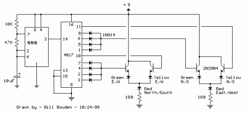
Build Your Own 4017 LED Traffic Light Circuit Diagram
Description
This LED traffic signal circuit regulates eight light-emitting diodes – specifically, red, yellow, and green – for traffic flow in both the northern/southern and eastern/western directions. The operational sequence is established utilizing a CMOS 4017 decade counter and a 555 timer. The outputs from pins 1 through 4 of the counter are combined using eight 1N914 diodes. Consequently, the (Red - North/South) and (Green - East/West) LEDs are activated during the initial four clock cycles. The fifth clock cycle (pin 10) triggers illumination of both the (Yellow - East/West) and (Red - North/South) LEDs. The remaining clock cycles, spanning counts 6 through 9, are also combined using diodes to manage the (Red - East/West) and (Green - North/South) LEDs. Finally, the tenth clock cycle (pin 11) controls the (Red - East/West) and (Yellow - North/South) LEDs. The duration of the red and green signals is four times longer than the duration of the yellow signal, and the overall cycle length can be fine-tuned using the 47K resistor. The eight 1N914 diodes could be replaced with a dual 4 input OR gate (CD4072).
