- Relay Control with Logic Levels: Resistor Guide
- Monostable Flip Flop Circuit: Build Your Timing Delay
- Bistable Flip Flop Circuit: Build Your Stable Electronic Switch
- Set/Reset Flip Flop: Build Your 1-Bit Memory Circuit
- Build Your Own 4017 LED Traffic Light Circuit Diagram
- Build Your 7490 Frequency Divider: A Powerful 2-10 Circuit
- Frequency Doubler: Build Your 4011 Circuit Diagram
- Build a 4069 Frequency Doubler Circuit Diagram
- Build a 50Hz to 25Hz Frequency Divider Circuit
- Build Your Classic MM5314N Digital Clock Circuit
- Step Km Counter Circuit Design
- Build Your 7 Segment LED Counter with a 74LS90
- Build Your Pocket Distance Counter!
Monostable Flip Flop Circuit: Build Your Timing Delay
Description
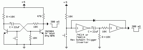
The monostable multivibrator, also referred to as a ‘one-shot’, is employed to generate a single pulse each time it’s activated. It’s frequently utilized to de-bounce mechanical switches, ensuring that only a single rising and falling edge occurs for each switch closure, or for generating delays in timing applications. Within the discrete circuit, the primary transistor typically conducts while the secondary side remains inactive. Activating the switch grounds the base of the conducting transistor, causing it to deactivate and resulting in a rise in the collector voltage. As the collector voltage increases, the capacitor begins to charge through the base of the opposing transistor, leading to it switching on and producing a low state at the output. The low output state maintains the primary transistor inactive until the capacitor’s current diminishes below the level needed to sustain the output stage’s saturation. When the output side initiates deactivation, the ascending voltage causes the primary transistor to return to its conducting state, reducing the voltage at its collector and triggering the capacitor to discharge through the 10K resistor (emitter to base). The circuit then stabilizes until the subsequent input. The one-shot circuit on the right utilizes two logic inverters interconnected via the timing capacitor. When the switch is closed, or the input becomes negative, the capacitor charges through the resistor, creating an initial high signal at the input of the second inverter, which generates a low output state. This low output state is connected back to the input through a diode, preserving a low input after the switch is opened until the voltage drops below 1/2 Vcc at pin 3, at which point the output and input return to a high state. The capacitor then discharges through the resistor (R) and the circuit stabilizes until the next input arrives. The 10K resistor in series with the inverter input (pin 3) minimizes the discharge current through the input protection diodes. This resistor might not be necessary with smaller capacitor values. Integrated circuits such as the 74HC14 (TTL) are commonly used to implement this functionality, providing precise timing control. These ICs typically include features like adjustable pulse width and high-speed operation, offering improved performance compared to discrete transistor solutions. They are often preferred when higher speed and accuracy are required for timing applications. The 74HC14 is a versatile component, frequently found in applications such as digital delay circuits and various timing control systems, due to its reliable operation and ease of integration. Integrated circuits such as the LM555 (CMOS) are commonly used to implement this functionality, providing precise timing control. These ICs typically include features like adjustable pulse width and high-speed operation, offering improved performance compared to discrete transistor solutions. The 7414 is a versatile component, frequently found in applications such as digital delay circuits and various timing control systems, due to its reliable operation and ease of integration. Integrated circuits such as the CD4014 (TTL) are commonly used to implement this functionality, providing precise timing control. These ICs typically include features like adjustable pulse width and high-speed operation, offering improved performance compared to discrete transistor solutions. The CD4014 is a versatile component, frequently found in applications such as digital delay circuits and various timing control systems, due to its reliable operation and ease of integration.
Note:
These circuits are not re-triggerable and the output duration will be shorter than normal if the circuit is triggered before the timing capacitors have discharged which requires about the same amount of time as the output. For re-triggerable circuits, the 555 timer, or the 74123 (TTL), or the 74HC123 (CMOS) circuits can be used.
