- Relay Control with Logic Levels: Resistor Guide
- Monostable Flip Flop Circuit: Build Your Timing Delay
- Bistable Flip Flop Circuit: Build Your Stable Electronic Switch
- Set/Reset Flip Flop: Build Your 1-Bit Memory Circuit
- Build Your Own 4017 LED Traffic Light Circuit Diagram
- Build Your 7490 Frequency Divider: A Powerful 2-10 Circuit
- Frequency Doubler: Build Your 4011 Circuit Diagram
- Build a 4069 Frequency Doubler Circuit Diagram
- Build a 50Hz to 25Hz Frequency Divider Circuit
- Build Your Classic MM5314N Digital Clock Circuit
- Step Km Counter Circuit Design
- Build Your 7 Segment LED Counter with a 74LS90
- Build Your Pocket Distance Counter!
Build a 50Hz to 25Hz Frequency Divider Circuit
Description
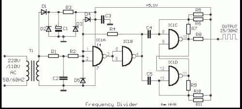
This represents a standard frequency divider employing a conventional T-flip-flop circuit, denoted as IC1 [4011]. The circuit’s operation restricts the negative half-cycle of a sinusoidal waveform and converts it into a square wave, subsequently dividing it by a factor of two. Consequently, for a frequency of 50 Hz, the output pulse will exhibit a frequency of 25 Hz. The power source for this circuit is +5V, and it does not require significant current draw.
Circuit diagram
Part list
- R1= 10Kohm
- R2= 100Kohm
- R3= 680 ohm
- R4= 1Mohm
- R5-6-7= 100Kohm
- R8= 47 ohm
- R9-10-11= 100Kohm
- C1= 1000uF 25V
- C2-3= 100nF 100V ceramic
- C4-5= 100pF ceramic
- IC1= 4011
- T1= 110/220Vac //8V 100mA
- D1-2= 1N4007
- D3= 5.1V 0.5W Zener
- D4-5= 1N4148
IC1 – 4011
The 4011 is a versatile quadruple J-K flip-flop integrated circuit. It is a widely used component in digital logic circuits. This particular IC is utilized here to implement the frequency dividing functionality of the circuit. The 4011 operates based on clock signals, allowing the circuit to shift between different states and generate the desired square wave output. Its operation is controlled by the input clock signals, creating a bistable multivibrator which is essential for the circuit's operation. The device is typically available in a DIP-14 package, providing easy access to all pins.
**Warning:** This circuit diagram is for informational purposes only. Building and operating electrical circuits involves potential hazards. Improper construction or use could result in electric shock, fire, or damage to equipment. Always exercise caution and consult with qualified professionals before undertaking any electrical projects.
Part list
- R1= 10Kohm
- R2= 100Kohm
- R3= 680 ohm
- R4= 1Mohm
- R5-6-7= 100Kohm
- R8= 47 ohm
- R9-10-11= 100Kohm
- C1= 1000uF 25V
- C2-3= 100nF 100V ceramic
- C4-5= 100pF ceramic
