- Build Your Own Battery-Powered Night Lamp Circuit
- Build Your Own Ultra Bright LED Lamp Circuit
- Dual LED Pilot Light Circuit: Build Your Appliance Monitor
- Build Your Solar Lamp: PR4403 Circuit Diagram
- Multicolor LED Circuit for Disk Drive Status
- Mains LED Circuit: 100-240V AC Schematic
- Automatic Emergency Light Circuit Diagram – Build Your Own!
- LED Torch Circuit Diagram: 80x Longer Battery Life
- Build Your Doorbell Warning Circuit: 22 Ohm Resistor Design
- Build a 120V Line-Powered White LED Circuit (2.4K Resistor)
- Build a 5V AC to LED Circuit with Safety
Automatic Emergency Light Circuit Diagram – Build Your Own!
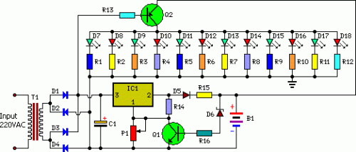
Circuit diagram:
Description
This white-LED-based emergency light provides several benefits. Firstly, it delivers a significant level of brightness thanks to the use of white LEDs. Secondly, the illumination automatically activates when the utility power fails and ceases operation when the mains supply returns. Thirdly, it incorporates an integrated battery charging system; this system automatically halts charging once the battery reaches full capacity. The charger power supply section is constructed around a 3-terminal adjustable regulator integrated circuit, the LM317 (IC1), while the LED driver section is built around the transistor, BD140 (Q2).
Within the charger power supply section, the alternating current input is reduced by T1 to generate a 9V, 500mA output, which is then supplied to the bridge rectifier, consisting of diodes D1 through D4. A filter capacitor, C1, minimizes any fluctuations in the voltage. This unregulated DC voltage is directed to input pin 3 of IC1, providing the charging current via diode D5 and a limiting resistor, R15. The output voltage is finely tuned by adjusting potentiometer P1, ensuring the desired charging current is delivered to the battery. Once the battery reaches 6.8V, diode D6 conducts, establishing a pathway for the charging current from IC1 through transistor QT1 to ground, thereby ceasing battery charging. When utility power is available, the base of Q2 remains energized, preventing Q2 from conducting, and consequently, the LEDs remain unlit.
Conversely, when the mains power source fails, the base of Q2 is de-energized, prompting it to conduct. This causes all the LEDs to illuminate. The utility power supply then charges the battery while simultaneously maintaining the LEDs' glow due to Q2 remaining switched off. During periods of power outage, the charging portion of the circuit becomes inactive, and the B1 supply sustains the LEDs’ illumination. Assemble the circuit on a standard printed circuit board and enclose it within a protective cabinet, accommodating sufficient space for the battery and switches. The circuit has been tested with twelve 10mm white LEDs. Expanding the number of LEDs is possible, provided the total current drawn does not exceed 1.5A. The driver transistor Q2 is capable of delivering up to 1.5A with a suitable heat-sink design implemented.
Parts:
- P1 = 2.2K
- R1-R12 = 100R-1/2W
- R13 = 1K-1/2W
- R14 = 180R-1/2W
- R15 = 16R/5W
- R16 = 1.2K
- C1 = 1000uF-25V
- D1-D5 = 1N4007
- D6 = 6.8V-0.5W Zener
- D7-D18 = 10mm- White LEDs
- Q1 = BC548
- Q2 = BD140
- B1 = 6V-4.5Ah Battery
- IC1 = LM317
- T1 = 9Vac-Transformer
