- Build Your Own Battery-Powered Night Lamp Circuit
- Build Your Own Ultra Bright LED Lamp Circuit
- Dual LED Pilot Light Circuit: Build Your Appliance Monitor
- Build Your Solar Lamp: PR4403 Circuit Diagram
- Multicolor LED Circuit for Disk Drive Status
- Mains LED Circuit: 100-240V AC Schematic
- Automatic Emergency Light Circuit Diagram – Build Your Own!
- LED Torch Circuit Diagram: 80x Longer Battery Life
- Build Your Doorbell Warning Circuit: 22 Ohm Resistor Design
- Build a 120V Line-Powered White LED Circuit (2.4K Resistor)
- Build a 5V AC to LED Circuit with Safety
Dual LED Pilot Light Circuit: Build Your Appliance Monitor
Description
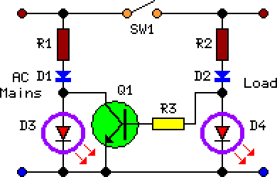
This circuit was developed according to a specific requirement and may prove advantageous for individuals desiring to observe the status of a device – specifically, a red light activated when an electrical device is operational and a green light illuminated when the same device is in an inactive state. Monitoring any appliance utilizing alternating current can be achieved with this design, provided a suitable AC switch, able to handle the complete load current, is employed for SW1. When SW1 is closed, the load and D4 are powered, Q1 is driven to its maximum conductivity, effectively shorting D3 and preventing its activation.
Circuit Diagram:
Parts:
- R1 = 15K-1W
- R2 = 15K-1W
- R3 = 6.8K
- D1 = 1N4007
- D2 = 1N4007
- D3 = Green
- D4 = Red LED
- Q1 = BC337
- SW1 = SPST Mains Switch
Integrated Circuit Details
The BC337 is a general-purpose NPN transistor. It’s a three-terminal device – Base (B), Collector (C), and Emitter (E). This particular transistor is frequently used in switching applications due to its moderate gain and relatively high current handling capability. It’s commonly employed here to control the flow of current to the LED, acting as a switch controlled by the input signal. Its performance characteristics – such as collector current, collector-emitter voltage, and gain – are crucial to consider when designing circuits utilizing this component. The BC337 is a widely available and cost-effective transistor, making it a popular choice for many circuit designs, providing a good balance between performance and price.
Notes:
- The values of R1 and R2 have been adjusted to 15K ohms, 1W, to optimize performance for a 115Vac power supply.
- The AC switch (SW1) needs to be able to withstand the entire current and voltage of the connected appliance.
A security warning is provided regarding the potential hazards associated with mains voltage circuits. Exercise extreme caution when working with electrical systems and ensure that all work is performed by qualified personnel only. Improper wiring or handling of mains voltage can result in serious injury or death. Always disconnect the power source before making any modifications to the circuit.
