- Build a 4-Stage Stabilised Power Supply with Short Circuit Protection
- Build Your Own 3-30V Adjustable DC Power Supply
- Build Your Own 9V 2A DC Power Supply Circuit
- Build Your Own: 1.3-22V Adjustable Power Supply Circuit
- Adjustable Current Limit: Dual Power Supply Design
- Build Your High-Performance 170V Hybrid Amplifier Power Supply
- Build Your 15V Regulated Power Supply Circuit – Simple & Powerful
- Transformerless 5V Power Supply Design Guide
- Build Your Own 24V 2A Variable DC Power Supply
- High Voltage Regulator: Design and Short Circuit Protection
- Boost Regulator Current: Design Your 1500mA Circuit
- Extend Smoke Alarm Battery Life with 12V Power
- 2 Watt Switching Power Supply: Build Your Own Circuit
- Variable Voltage & Current Power Supply: Build Your 0-3 Amp Circuit
- Build Your 24 Volt 3 Amp Power Supply Circuit
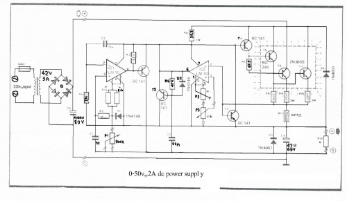
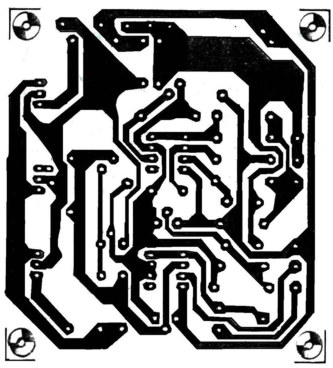
Build Your 0-50V 2A Bench Power Supply Circuit
Circuit Diagram
The LM10 integrated circuit is utilized here due to its inherent reference voltage functionality, which proves beneficial for constructing a direct current power supply. Employing two ICs enables the generation of diverse output voltages alongside adjustable current levels. This circuit incorporates protective measures against short-circuit conditions. P2 facilitates the control of the current within a range of 0 to 2 Amperes. The output voltage stability is achieved through resistor R4 connected to the negative terminal of the operational amplifier, and resistors R2 and P1 connected to the positive terminal.Operational amplifier output controls transistor T1, preventing fluctuations in voltage. T1 can alter the amperage through resistor R6, controlling the voltage of transistors T5 and T4. Pin 1 serves as the reference voltage, with a small current (100uA) passing through resistor P1. This lost voltage, calculated as Vlose p1=100uA*Rp1, is utilized in regulating the output voltage rate, comparing it with the reference voltage provided by P3. Transistor T3 protects against short circuits using resistor R11. To reduce the output voltage to 0V, a 470-ohm resistor is paralleled in the output. The minimum allowable voltage is 0.4 volts, while the maximum output voltage is fixed by resistor R1b and should not exceed 50 volts. Consequently, a transformer providing 36 Volts, 3 Amperes, and incorporating a 4700uF capacitor is recommended. Transistors T6, T5, and T7 require heatsinks for effective heat dissipation.
Parts
- R1a = 2.2 K
- R1b = read the text
- R2 = 10 K
- R3, R7 = 3.3 k
- R4 = 390 Ohm
- R5 = 47 K
- R6 = 3.3 K 1Watt
- R8 = 180 Ohm
- R9, R10 = 0.47 Ohm 3Watt
- R11 = 0.075 Ohm 2Watt
- R12 = 470 Ohm
- P1 = 500K liner potentiometer
- P2 = 4.7 K potentiometer
- P3 = 10 K potentiometer
- C1 = 1nF
- C2 = 10nF
- C3 = 22nF
- C4 = 47mF 63v electrolytic
- C5 = 4700mF 80v electrolytic
- T1, T2 = BC161
- T3, T4 = BD141
- T5 = BD241
- T6, T7 = 2V3055
- D1, D2 = 1N4148
- D3, D4 = 1N4001
- IC1, IC2 = LM10C
circuit from http://www.electronics-lab.com/

