- Build a 4-Stage Stabilised Power Supply with Short Circuit Protection
- Build Your Own 3-30V Adjustable DC Power Supply
- Build Your Own 9V 2A DC Power Supply Circuit
- Build Your Own: 1.3-22V Adjustable Power Supply Circuit
- Adjustable Current Limit: Dual Power Supply Design
- Build Your High-Performance 170V Hybrid Amplifier Power Supply
- Build Your 15V Regulated Power Supply Circuit – Simple & Powerful
- Transformerless 5V Power Supply Design Guide
- Build Your Own 24V 2A Variable DC Power Supply
- High Voltage Regulator: Design and Short Circuit Protection
- Boost Regulator Current: Design Your 1500mA Circuit
- Extend Smoke Alarm Battery Life with 12V Power
- 2 Watt Switching Power Supply: Build Your Own Circuit
- Variable Voltage & Current Power Supply: Build Your 0-3 Amp Circuit
- Build Your 24 Volt 3 Amp Power Supply Circuit
Build a Current Limiter: Protect Your PSU at 70mA
Description
This circuit allows you to establish a maximum limit on the maximum output current supplied by your power supply unit. It’s particularly valuable when initiating a project for the first time, or when conducting a prolonged soak-test. By defining an upper bound on the current delivered by your PSU – you safeguard both the power supply and any device connected to it. This provides a straightforward and affordable alternative to the Current Limiting Power Supply
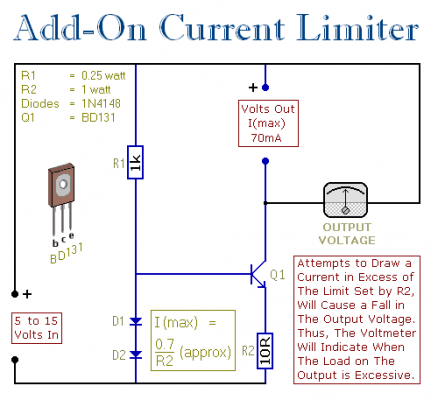
The fundamental schematic is illustrated in the initial diagram. The two diodes determine the highest achievable voltage across the base of the Power Transistor, typically around 1.4 volts. Consequently, the maximum voltage across R2 is consistently fixed at approximately 0.7 volts. If R2 is valued at 10 ohms – the greatest possible emitter current is (0.7 ÷ 10) - roughly 70mA.
Given that the collector current is generally equivalent to the emitter current – it's impossible to draw more than 70mA from the output terminals. Attempting to do so results in a reduction of the output voltage.
A BD131 was utilized due to availability at the time. However, any NPN Power Transistor with comparable – or superior – specifications would function effectively. There was no specific rationale behind selecting a 70mA maximum limit. To adjust the current limit, modify the value of R2. The relevant formula is presented in the diagram. Always remember that elevating the current also increases the wattage.
The subsequent schematic incorporates several supplementary features. If you prefer not to employ a voltmeter on the output – an LED can be utilized instead. Should the output voltage decrease – the LED will dim or cease to illuminate entirely. This provides sufficient notification that the load on the output is exceeding permissible limits.
When the Current Limiter requires unattended operation – for instance, during a soak-test – a Buzzer proves useful. If a problem arises – and the output voltage falls by 2 volts or more – the circuit will trigger an audible alarm.
Veroboard Layout
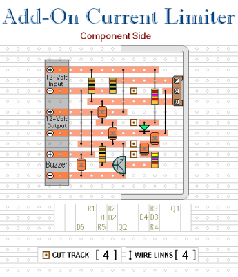
The presented layout pertains to the second schematic; it’s designed to be adaptable. To omit the LED feature – simply remove the LED and R3. To disable the alarm functionality – eliminate D3, D4, D5, R4, R5 & Q2.

