- Build a 4-Stage Stabilised Power Supply with Short Circuit Protection
- Build Your Own 3-30V Adjustable DC Power Supply
- Build Your Own 9V 2A DC Power Supply Circuit
- Build Your Own: 1.3-22V Adjustable Power Supply Circuit
- Adjustable Current Limit: Dual Power Supply Design
- Build Your High-Performance 170V Hybrid Amplifier Power Supply
- Build Your 15V Regulated Power Supply Circuit – Simple & Powerful
- Transformerless 5V Power Supply Design Guide
- Build Your Own 24V 2A Variable DC Power Supply
- High Voltage Regulator: Design and Short Circuit Protection
- Boost Regulator Current: Design Your 1500mA Circuit
- Extend Smoke Alarm Battery Life with 12V Power
- 2 Watt Switching Power Supply: Build Your Own Circuit
- Variable Voltage & Current Power Supply: Build Your 0-3 Amp Circuit
- Build Your 24 Volt 3 Amp Power Supply Circuit
13.8V 10A Power Supply Build Guide
Circuit diagram
Description
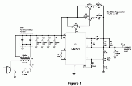
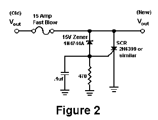
Amateurs sometimes choose to build their own power supplies rather than purchasing one from a reputable ham radio retailer. The benefit of constructing your own power supply is that it allows for learning about its operation and provides a simpler method for troubleshooting and repairing other power supply units within a ham radio station. A significant cost advantage is only realized if a large power transformer and a substantial heat sink can be obtained at a drastically reduced price. However, self-construction does offer the flexibility to customize the circuit and potentially enhance its reliability beyond commercially available units. The circuit depicted in Figure 1 provides a 10 amp (12 amp surge) output with performance that meets or exceeds that of commercial units. This circuit incorporates a current limiting feature, representing a more dependable system compared to many commercial power supplies. Similar to other commercial units, this circuit employs the LM723 integrated circuit (IC), which delivers excellent voltage regulation. The circuit utilizes three pass transistors, necessitating heat sinking. Resistor R9 facilitates fine-tuning of the output voltage to exactly 13.8 volts, and the resistor network formed by resistors R4 through R7 controls the current limiting function. The LM723 limits current when the collector current of the pass transistors approaches 0.7 volts. To minimize expenses, many commercial units rely on the forward current gain (HFE) of the pass transistors to determine the current limiting. A key drawback of this approach is that the HFE of the transistors increases as they heat up, potentially leading to a thermal runaway condition and a failure of the pass transistors. Because this circuit samples the collector current of the pass transistors, thermal runaway is not a concern, making it a more dependable power supply. The only adjustment required is setting R9 to the desired output voltage, ranging from 10 to 14 volts. A 1K potentiometer (RS271-280) can be used for this purpose if preferred. Resistor R1 primarily enhances temperature stability and can be eliminated by connecting pins 5 and 6 of IC-1 together. Although not strictly necessary due to the chosen current limiting circuit, overvoltage protection can be added to the circuit by connecting the circuit depicted in Figure 2 to the output voltage (Vout). Overvoltage can only occur if transistors Q2 or Q3 fail with a short circuit between the collector and emitter. However, collector-emitter shorts are less likely to occur; it is more probable that the transistors will open up when they fail.
I actually tested this design and deliberately destroyed several 2N3055 transistors by shorting the emitters to ground. In all instances, the transistors opened up and no collector-emitter short occurred. In any event, the optional circuit in Figure 2 provides added peace of mind when a costly radio is used with this power supply. The circuit in Figure 2 detects voltage exceeding 15 volts and triggers the zener diode to conduct. Upon conduction, the gate of the silicon-controlled rectifier (SCR) is activated, causing the SCR to short and blow the 15 amp fuse, thereby shutting off the output voltage. A 2N6399 (Tech America) was used for the SCR in the prototype, but any suitable SCR can be utilized. While overvoltage protection is advisable, it should not be considered a substitute for substantial heat sinks. I personally believe the best protection against overvoltage is the use of large heat sinks and a reliable current limiting circuit. It is important to use large heat sinks combined with heat sink grease for the 2N3055 transistors. I have employed this power supply in my ham radio station for several months on a variety of transceivers, ranging from HF, VHF to UHF, with excellent results and absolutely no hum. This power supply will be a welcome addition to your ham radio station and will substantially enhance your knowledge of power supplies.
Parts
- R1 1.5K ¼ Watt Resistor (optional, tie pins 6 & 5 of IC1 together if not used.)
- R2, R3 0.1 Ohm 10 Watt Resistor (Tech America 900-1002)
- R4 270 Ohm ¼ Watt Resistor
- R5 680 Ohm ¼ Watt Resistor
- R6, R7 0.15 Ohm 10 Watt Resistor (Tech America 900-1006)
- R8 2.7K ¼ Watt Resistor
- R9 1K Trimmer Potentiometer (RS271-280)
- R10 3.3K ¼ Watt Resistor
- C1, C2, C3, C4 4700 Microfarad Electrolytic Capacitor 35 Volt (observe polarity)
- C5 100 Picofarad Ceramic Disk Capacitor
- C6 1000 Microfarad Electrolytic Capacitor 25 Volt (observe polarity)
- IC1 LM723 (RS276-1740) Voltage Regulator IC. Socket is recommended.
- Q1 TIP3055T (RS276-2020) NPN Transistor (TO-220 Heat Sink Required)
- Q2, Q3 2N3055 (RS276-2041) NPN Transistor (Large TO-3 Heat Sink Required)
- S1 Any SPST Toggle Switch
- F1 3 Amp Fast Blow Fuse
- D1-D4 Full Wave Bridge Rectifier (RS276-1185)
- T1 18 Volt, 10 Amp Transformer Hammond #165S18 (Tech America 900-5825)
circuit from http://www.electronics-lab.com/

