- Build a 4-Stage Stabilised Power Supply with Short Circuit Protection
- Build Your Own 3-30V Adjustable DC Power Supply
- Build Your Own 9V 2A DC Power Supply Circuit
- Build Your Own: 1.3-22V Adjustable Power Supply Circuit
- Adjustable Current Limit: Dual Power Supply Design
- Build Your High-Performance 170V Hybrid Amplifier Power Supply
- Build Your 15V Regulated Power Supply Circuit – Simple & Powerful
- Transformerless 5V Power Supply Design Guide
- Build Your Own 24V 2A Variable DC Power Supply
- High Voltage Regulator: Design and Short Circuit Protection
- Boost Regulator Current: Design Your 1500mA Circuit
- Extend Smoke Alarm Battery Life with 12V Power
- 2 Watt Switching Power Supply: Build Your Own Circuit
- Variable Voltage & Current Power Supply: Build Your 0-3 Amp Circuit
- Build Your 24 Volt 3 Amp Power Supply Circuit
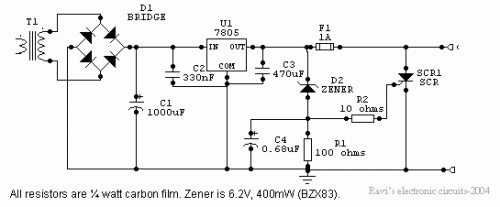
TTL Power Supply with Zener Crowbar Protection Circuit
Circuit diagram
Overview
Power supplies intended for use with TTL logic circuitry must be protected against over-voltage, which can quickly damage TTL chips. The duration of over-voltage required to destroy TTL chips is too brief for conventional fuses to trigger, necessitating alternative semiconductor circuits for protection against stabilizer failures leading to excessive voltage. This is the most prevalent type of stabilizer failure, thus protection is crucial for any significant TTL circuit. While many modern digital circuits utilize MOS devices, which are less susceptible to over-voltage damage, it’s uncommon to find large digital circuits without TTL devices.
In the circuit shown below, if the voltage at the output terminals exceeds 6.2V, the zener diode conducts charging capacitor C4. This voltage will activate the silicon-controlled rectifier (SCR), rapidly shorting across the supply rails and blowing the fuse.
Circuit Description
The regulator IC is a commonly used fixed voltage regulator, such as the LM7805. The 7805 is a three-pin regulator needing a minimum input voltage of 7.5V to maintain stabilization, with a maximum input voltage of 35V. The maximum load current is 1A, and input voltage regulation typically results in a variation of 3-7mV for changes between 7.1V and 25V. Load current regulation results in a variation of approximately 10mV for changes between 5mV and 1.5A. The noise voltage within the 10Hz to 100KHz range is 40-50uV, and ripple rejection reaches around 70db. The maximum junction temperature is 215 degrees C, and the thermal resistance from junction to case is 5 degrees C/W. This stabilizer is frequently utilized in power supplies for digital equipment.
The capacitors connected to each side of the IC are essential for suppressing oscillations and should not be omitted. Specifically, the 330nF capacitor at the input must be connected across the shortest possible path at the IC pins.
A TIC 106A SCR was chosen due to its ability to handle an anode current up to 4A at 100V, while its gate requires only about 200uA to activate it. The SCR remains ‘on’ for only a brief period, eliminating the need for a heat sink. Using alternative SCR types may not exhibit similar characteristics. Most SCRs with high anode current ratings possess insensitive gates. SCRs with lower anode current ratings will require a heat sink.
The fuse rating depends on the power supply’s output current. Assuming a maximum output current of approximately 200 to 300 mA, a 500mA fuse can be used. The switching voltage of the SCR is largely determined by the value of the zener diode. Experimentation with different zener values can be conducted to protect other circuit types. 4000 series CMOS ICs have supply voltage limits of 15V (AE suffix) or 20V (BE suffix), and crowbar protection can be implemented for these devices as well.
Component Details
**Silicon-Controlled Rectifier (SCR)**
A silicon-controlled rectifier (SCR) or thyristor is a semiconductor device that conducts current in one direction when given a trigger signal. It acts like an electronically controlled switch. These devices are commonly used in power control applications, such as controlling motor speed or switching AC power to DC. The TIC 106A SCR is capable of handling an anode current up to 4A at 100V, while its gate requires only about 200uA to fire it.
**Zener Diode**
A zener diode is a type of diode that, when reverse-biased, maintains a relatively constant voltage across its terminals. It is characterized by its ‘zener voltage,’ which is the voltage at which it begins to conduct significant current. Zener diodes are frequently employed for voltage regulation, providing a stable reference voltage. The value of the zener diode determines the voltage at which the SCR will activate, offering protection against over-voltage conditions.
**4000 Series CMOS ICs**
4000 series CMOS ICs are a family of integrated circuits that utilize complementary metal-oxide-semiconductor (CMOS) technology. These ICs are widely used in digital logic circuits and microprocessors. The suffix ‘AE’ or ‘BE’ in the IC’s designation (e.g., 74HC series) indicates the supply voltage limits: ‘AE’ ICs operate with a 15V supply voltage, while ‘BE’ ICs operate with a 20V supply voltage. These devices are commonly used for switching and logic operations in various electronic systems.
circuit from http://www.electronics-lab.com/
