- Build a 4-Stage Stabilised Power Supply with Short Circuit Protection
- Build Your Own 3-30V Adjustable DC Power Supply
- Build Your Own 9V 2A DC Power Supply Circuit
- Build Your Own: 1.3-22V Adjustable Power Supply Circuit
- Adjustable Current Limit: Dual Power Supply Design
- Build Your High-Performance 170V Hybrid Amplifier Power Supply
- Build Your 15V Regulated Power Supply Circuit – Simple & Powerful
- Transformerless 5V Power Supply Design Guide
- Build Your Own 24V 2A Variable DC Power Supply
- High Voltage Regulator: Design and Short Circuit Protection
- Boost Regulator Current: Design Your 1500mA Circuit
- Extend Smoke Alarm Battery Life with 12V Power
- 2 Watt Switching Power Supply: Build Your Own Circuit
- Variable Voltage & Current Power Supply: Build Your 0-3 Amp Circuit
- Build Your 24 Volt 3 Amp Power Supply Circuit
Build Your Powerful 50V 3A Stabilized Power Supply Circuit
Description
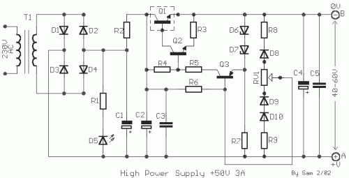
Frequently, the need arises for a stable, precisely regulated power supply alongside a high, relatively elevated output voltage. These specifications fulfill our circuit’s requirements. This design is capable of delivering an output ranging from +40V to +60V at a current capacity of 3A, with concurrent stabilization. The materials utilized are straightforward, minimizing manufacturing complexities; careful attention to particular points is sufficient. 1] For output voltages smaller than +50V up to +40V, the Q1 component necessitates an adequately sized heatsink. 2] For output voltages exceeding +50V up to +70V, the stabilization performance is not optimal. Consequently, the ideal output voltage is considered to be between +45V and +60V. Within the circuit, a potentiometer RV1 is employed to adjust the output voltage between +40V and +70V; however, it may be replaced by two fixed resistors upon completion of the regulation, to achieve the desired level of precision. This adjustment is due to the gradual shift in output voltage, often reaching 3V, when the potentiometer is in use. WARNING!!! The positive output terminal is located at point [A], and the 0V terminal is at point [B]; these should never be connected to ground.
Circuit Diagram
Part List
- R1=10Kohm
- R2=1 ohm 5W
- R3=3.9 ohms 1W
- R4=6.8Kohm 1W
- R5=390 ohms 1W
- R6=100Kohm 0.5W
- R7=1.2Kohm 1W
- R8=1.8Kohm 0.5W
- R9=3.3Kohm 0.5W
- RV1=470 ohms pot.
- C1-2-4=4700uF 100V
- C3-5=100nF 250V MKT
- Q1=2N3055 on heatsink
- Q2=BD162 or BD243 or BD543
- Q3=BC303 or BC461
- D1....4=Bridge 15A
- D5=LED RED 5mm
- D6-7=10V 1W Zener
- D8-9-10=1N4007
- T1=230Vac / 55V 3A
