- Build a 4-Stage Stabilised Power Supply with Short Circuit Protection
- Build Your Own 3-30V Adjustable DC Power Supply
- Build Your Own 9V 2A DC Power Supply Circuit
- Build Your Own: 1.3-22V Adjustable Power Supply Circuit
- Adjustable Current Limit: Dual Power Supply Design
- Build Your High-Performance 170V Hybrid Amplifier Power Supply
- Build Your 15V Regulated Power Supply Circuit – Simple & Powerful
- Transformerless 5V Power Supply Design Guide
- Build Your Own 24V 2A Variable DC Power Supply
- High Voltage Regulator: Design and Short Circuit Protection
- Boost Regulator Current: Design Your 1500mA Circuit
- Extend Smoke Alarm Battery Life with 12V Power
- 2 Watt Switching Power Supply: Build Your Own Circuit
- Variable Voltage & Current Power Supply: Build Your 0-3 Amp Circuit
- Build Your 24 Volt 3 Amp Power Supply Circuit
Build Your Own 5V Regulated Power Supply Circuit
Description
This circuit constitutes a compact +5V power supply, beneficial for experimenting with digital electronics. Small, inexpensive wall transformers providing variable output voltage are readily accessible from electronics shops and supermarkets. These transformers are easily obtainable, however, their voltage regulation is typically poor, rendering them unsuitable for digital circuit experimentation unless enhanced regulation is implemented.
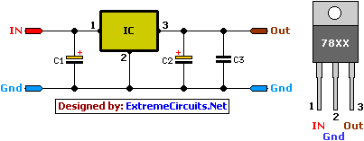
The following circuit represents the solution to the outlined problem. This circuit provides a +5V output at approximately 150 mA of current, which can be increased to 1 A with supplemental cooling applied to the 7805 regulator chip. The circuit incorporates overload and thermal protection mechanisms. The capacitors must possess sufficient high voltage ratings to safely handle the input voltage delivered to the circuit. The circuit can be easily assembled, for instance, onto veroboard.
Circuit diagram:
Parts:
- C1 = 100uF-25V electrolytic capacitor, with a minimum voltage rating of 25V
- C2 = 10uF-25V electrolytic capacitor, with a minimum voltage rating of 6-16V
- C3 = 100nF-63V ceramic or polyester capacitor
- IC = 7805 regulator IC
IC's Pinout :
- Unregulated voltage in
- Ground (See Diagram)
- Regulated voltage out
Circuit features:
- Provides a well-regulated +5V output, with an output current capacity of 100 mA
- Integrated overheating protection disables the output when the regulator IC becomes excessively hot
- Very simple and straightforward to construct
- Highly stable +5V output voltage, ensuring reliable operation
- Components are readily obtainable, utilizing only very common basic components
- Based on a datasheet example circuit, this circuit has been successfully employed as part of numerous electronics projects
- Used in electronic devices, a small laboratory power supply
- Supports a wide range of input unregulated DC 8-24V power supplies
- Minimal cost for the electronics components plus the input transformer expense
Modification Ideas
Increased Output Current:
To achieve an output current exceeding 150 mA, implement the following modifications to elevate the output current up to 1A.
- Replace the transformer supplying power to the circuit with a model capable of delivering the desired current output.
- Attach a heatsink to the 7805 regulator IC (ensure the heatsink is large enough to prevent overheating due to increased losses within the regulator).
Other Output Voltages:
To generate other voltages than +5V, modify the circuit by substituting the 7805 chips with a different regulator from the 78xx regulator family, possessing a varying output voltage. The final digits in the chip code denote the desired output voltage. Remember that the input voltage must be at least 3V greater than the regulator output voltage to ensure proper operation.
Integrated Circuits (ICs) - 7805
The 7805 is a three-terminal positive voltage regulator integrated circuit. It’s a very common and widely utilized component in various electronic circuits. It's a fixed 7V output regulator, meaning it consistently outputs a stable 7V DC voltage regardless of variations in the input voltage, as long as the input voltage is within its operating range. This makes it ideal for supplying a consistent power source to sensitive electronic components. It’s a simple, relatively inexpensive, and reliable device that is frequently found in power supplies, electronic devices, and prototyping circuits. Its robust design and small size contribute to its popularity.
