- Build a 4-Stage Stabilised Power Supply with Short Circuit Protection
- Build Your Own 3-30V Adjustable DC Power Supply
- Build Your Own 9V 2A DC Power Supply Circuit
- Build Your Own: 1.3-22V Adjustable Power Supply Circuit
- Adjustable Current Limit: Dual Power Supply Design
- Build Your High-Performance 170V Hybrid Amplifier Power Supply
- Build Your 15V Regulated Power Supply Circuit – Simple & Powerful
- Transformerless 5V Power Supply Design Guide
- Build Your Own 24V 2A Variable DC Power Supply
- High Voltage Regulator: Design and Short Circuit Protection
- Boost Regulator Current: Design Your 1500mA Circuit
- Extend Smoke Alarm Battery Life with 12V Power
- 2 Watt Switching Power Supply: Build Your Own Circuit
- Variable Voltage & Current Power Supply: Build Your 0-3 Amp Circuit
- Build Your 24 Volt 3 Amp Power Supply Circuit
Synchronous MOSFET Bridge Rectifier: Optimize 6V Performance
Description
The losses in a bridge rectifier can easily become significant when low voltages are being rectified. The voltage drop across the bridge is a good 1.5 V, representing a substantial 25% with an input voltage of 6V. Reduction of this loss is achievable by utilizing Schottky diodes, though further minimization to practically zero is possible with a synchronous rectifier. This involves replacing the passive ‘bridge’ rectifier with an active switching system.
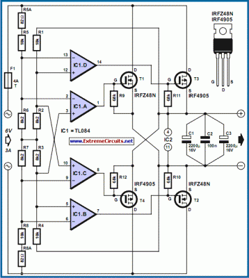
The principle is straightforward: whenever the instantaneous value of the input AC voltage exceeds the rectified output voltage, a MOSFET is switched on to allow current to flow from the input to the output. To achieve a full-wave rectifier, four FETs are employed instead of four diodes, mirroring the configuration of a standard bridge rectifier. R1–R4 constitute voltage dividers for the rectified voltage, while R5–R8 perform the same function for the AC input voltage. Upon the input voltage surpassing the rectified voltage, IC1d switches on MOSFET T3.
As in a conventional bridge rectifier, the MOSFET diagonally opposite T3 must also be switched on concurrently, a function managed by IC1b. The polarity of the AC voltage is reversed during the subsequent half-wave, triggering IC1c and IC1a to switch on T4 and T1, respectively. It’s notable that the input voltage dividers are not perfectly symmetrical. This slight reduction in the input voltage causes a delay in FET switching, which is preferable to premature activation, thereby minimizing losses.
Circuit diagram:
It is advised to utilize 1% resistors for the dividers, or, if available, even 0.1% resistors. The control circuit around the TL084 is powered from the rectified voltage, eliminating the need for an auxiliary supply. However, this raises the question of how such a system can operate. Initially, no voltage exists, and therefore the rectifier will not function, nor will any voltage ever be produced. Fortunately, a degree of luck is present. All FETs possess internal diodes, represented here with dashed outlines for clarity.
These internal diodes enable the circuit to initiate operation (with associated losses). The selection of FETs is not critically important; any suitable component can be utilized. The loss incurred depends primarily on the internal resistance. Modern FETs typically exhibit power dissipation values ranging from 20 to 50 mW. These devices can handle current flows on the order of 50 A. Despite this substantial current capacity, an average current of 5 A can easily generate peak currents of 50 A within the FETs.
The IRFZ48N (55 V @ 64 A, 16 mW), specified by the author, is no longer manufactured; however, it may still be obtainable. Alternatively, the IRF4905 can handle 55 V @ 74 A and possesses an internal resistance of 20 mR. At voltages exceeding 6 V, it’s recommended to increase the value of the 8.2-kR resistors, for example to 15 kR for 9V or 22 kR for 12 V.
circuit from http://www.extremecircuits.net/2010/05/power-mosfet-bridge-rectifier.html
