similar circuits
- 9V FM Transmitter Circuit: Build Your 100m Range
- Opamp VHF FM Transmitter Design (88-108 MHz)
- Build Your Own 50m Stereo Wireless Audio Link Circuit
- FM 45W Valve Transmitter Circuit Diagram – Build Your Own!
- Build Your Own 85-108 MHz Radio Transmitter!
- 3W FM Transmitter Schematic Blueprint
- Build Your Own 2 Transistor FM Voice Transmitter Circuit
- Build Your 88-108MHz 4W FM Transmitter Circuit
- FM Transmitter Bug: 4 Turns, 1.5 Turns – Build Your Circuit
- Build Your Own 98 MHz FM Beacon Transmitter
Build Your 88-108MHz 4W FM Transmitter Circuit
TECHNICAL SPECIFICATIONS:
- A stable DC voltage supply is provided: Vcc = 12~16V
- The emitted frequency ranges from 88~108MHz.
- Power consumption varies between 100~400mA.
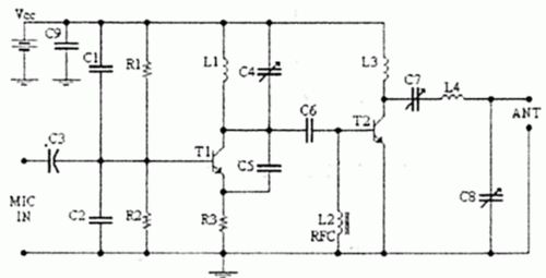
Circuit Diagram:
Detailed Components:
[h3]Integrated Circuits[/h3] Two 2N2219 integrated circuits are utilized in this circuit. These are small-signal transistors, commonly employed for amplification and switching applications due to their low voltage and current requirements. They are typically used as switches or amplifiers in low-power electronic circuits.Component List:
- Resistors are rated at 1/4W.
- R1, R2 – 10 kΩ
- R3 – 47 Ω
- C1, C2 – 1 nF
- C3 – 4.7 µF / 16V
- C4, C7, C8 – 0 ~ 45 pF trimmer capacitors
- C5, C6 – 10 pF
- C9 – 100 nF
- L1 – 4 turns, 7mm diameter *
- L3 – 3 turns, 7mm diameter *
- L4 – 5 turns, 7mm diameter *
- L2 – RFC (resistance 1 MOhm with wrapped around her inductor of enough coils from fine isolated wire. Scratch of utmost inductor and you stick in utmost the resistance making thus a parallel L-r circuit.)
- T1, T2 – 2N2219
- ANT – Simple dipole l/2.
- MIC IN – Microphone dynamic or other type. (It can also connected to a cassette player unit)
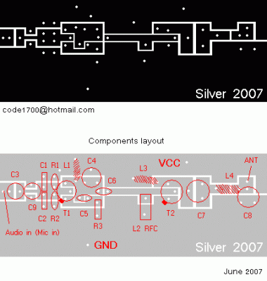
PCB:
Ensure the screen resolution is set to 1280 by 1024 before printing with Microsoft Paint to achieve the correct scale.
Regulations:
- The frequency is regulated with C4.
- C7 and C8 are utilized to adjust the aerial resistance (practically, these are adjusted to ensure clear voice reception in the radio as you improve audio quality).
Notes:
The T2 is intended for refrigerator use.
author: Kyriakos Kontakos, kkontak@hotmail.com
circuit from http://www.electronics-lab.com/
circuit from http://www.electronics-lab.com/

