- 9V FM Transmitter Circuit: Build Your 100m Range
- Opamp VHF FM Transmitter Design (88-108 MHz)
- Build Your Own 50m Stereo Wireless Audio Link Circuit
- FM 45W Valve Transmitter Circuit Diagram – Build Your Own!
- Build Your Own 85-108 MHz Radio Transmitter!
- 3W FM Transmitter Schematic Blueprint
- Build Your Own 2 Transistor FM Voice Transmitter Circuit
- Build Your 88-108MHz 4W FM Transmitter Circuit
- FM Transmitter Bug: 4 Turns, 1.5 Turns – Build Your Circuit
- Build Your Own 98 MHz FM Beacon Transmitter
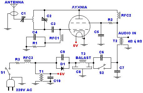
FM 45W Valve Transmitter Circuit Diagram – Build Your Own!
TECHNICAL SPECIFICATIONS:
- Power Supply Voltage: 220V AC
- Emission Frequency at FM: 88~108MHz
- Maximum Output Power: Up to 45W (excluding R3)
Circuit Diagram
In Detail:
More about components
The project incorporates a BY127 rectifier, a crucial component responsible for converting the alternating current (AC) from the power source into direct current (DC). This rectifier facilitates the operation of the lamp and allows for the transmission of audio signals. The BY127 is a general-purpose diode, widely used in low-power applications due to its reliability and relatively low forward voltage drop.
Transformers
Several transformers are utilized in this design. A 220V/6V-1A transformer is employed for voltage reduction, providing a safer and lower voltage output for the circuit. Additionally, a transformer with an 8W or 4W configuration is used, offering flexibility in power delivery. These transformers are essential for both voltage conversion and isolation, enhancing the safety and performance of the system. The specific characteristics of the transformers are vital for maintaining optimal operational parameters and minimizing potential hazards.
Inductors
The circuit utilizes several air inductors, each featuring 15 coils with a diameter of 8mm, constructed from 1mm wire. These inductors play a key role in shaping the resonant frequency of the antenna system, crucial for efficient radio frequency transmission and reception. Their precise dimensions and winding specifications contribute significantly to the overall performance of the system. The use of air core inductors minimizes parasitic capacitance, contributing to a cleaner signal.
MATERIALS:
- R1 15KW/2W
- R2 1KW/10W
- R3 1KW/10W (for maximum output, it should be replaced with a short circuit).
- C1 50pF trimmer
- C2 30pF trimmer
- C3 22pF/4KV
- C4, C6, C9 10nF/1KV
- C5, C7 1nF/1KV
- C8 100mF+100mF/450V (Double electrolytic)
- C9, C10 10nF
- RFC1, RFC2, RFC3 air Inductors: 15 coils diameter 8mm, from wire 1mm.
- T1 Transformer 220V/6V-1A
- T2 Transformer of configuration with being first 4 or 8W
- T3 Inductor with core ferrite (externally it resembles with small transformer but has a turn only).
- D1 BY127 rectifier
- Lamp 807 SYLV USA or EL34 or equivalent
- ANTENNA Simple dipole L/2. (L= wave length)
- S1 Main switch of catering.
- S2 Switch of catering of rise (him we close after zestacej' the thread).
REGULATIONS:
- Frequency adjustment is performed using C2.
- Resistance of the aerial is adjusted with C1 to ensure clear audio reception, effectively allowing you to hear your voice in the radio.
NOTES:
- Optimal performance is achieved when the power supply is connected via a 220V/220V isolation and safety 1A transformer, prioritizing safety and operational efficiency.
- Without R3, the output power increases, but the hum at 50Hz also increases due to the simplified design.
- The Audio In signal can originate from a kasseto'fwno or another powerful source. If a microphone is used, it is typically connected to a preceding amplifier to achieve an approximate power output of 8W.
circuit from http://www.electronics-lab.com/
